Friday, November 22, 2013
What is an Autotransformer
WHAT IS AN AUTOTRANSFORMER? HOW IS IT IMPLEMENTED?
An autotransformer is a type of transformer in which a single inductor coil is used. It has a single continuous winding of coil, with a connection point between the primary and secondary sides. This connection point is called tap. The tap has its own characteristics: an adjustable joint that is used vary the number of turns and influence the turn ratio, to either step up and step down the voltage across the device. This feature can be used to provide a variable voltage to a load connected to the transformer.
An autotransformer is a type of transformer in which a single inductor coil is used. It has a single continuous winding of coil, with a connection point between the primary and secondary sides. This connection point is called tap. The tap has its own characteristics: an adjustable joint that is used vary the number of turns and influence the turn ratio, to either step up and step down the voltage across the device. This feature can be used to provide a variable voltage to a load connected to the transformer.
Construction:
The main difference in the construction of autotransformers for a step down or step up voltages lies in the connection between the voltage source and the connected load with the single inductor coil. Variable voltage is produced in this way.
Some key mathematical expressions for step down and step up transformers are given below:
• For a step down transformer circuit, the voltage ratio is given by:
V1/V2 = (N1+N2) / N2
• And the current ratio is given as:
I1/I2 = N2 / (N1+N2)
• For a step up transformer circuit, the voltage ratio is given by:
V1/V2 = N1 / (N1+N2)
• And the current ratio is given as:
I1/I2 = (N1+N2) / N1
Where V1 = Voltage across the inductor coil of an autotransformer
V2 = voltage across the load connected to the autotransformer
I1 = Electric current passing through the inductor coil
I2 = Electric current passing through the load
N1 = Number of turns of coil on the primary side
N2 = Number of turns of coil on the secondary side
Comparing an autotransformer with a conventional transformer:
An autotransformer is a type of power transformer. It can transfer a larger apparent power than a two-inductor coil-wound transformer. When compared to standard transformers, autotransformers tend to be smaller in size and lighter in weight. However, a major disadvantage of an autotransformer is its lack of electrical isolation between primary and secondary windings due to the presence of a single winding inductor coil. This property of lacking electrical isolation does not make an autotransformer a useless device - application where electrical isolation is not required do exist.
A full range of transformers and autotransformers are supplied by element 14, through their business partner Panduit.
Stereo 30W STK ICs amplifier circuit

Component List :This amplifier circuit based on IC STK ic used in which the manifold. And on this circuit ic STK has many similarities, you can use the STK430 ICs, 433, 435, 437, 439, 441, 443, 4332, 4352, 4362, 4372, 4392. Between the specify type IC STK, which has the excellent performance is STK433 and STK443 because it has output, and high amperage, and voltage problems Suplly but I chose IC STK443 because maximum voltage up to 70 volts, compared with the others that just under 60 volts. For a list of components can seen below.
Resistor
R1_____1KΩ
R2_____1KΩ
R3_____120Ω
R4_____120Ω
R5_____330KΩ
R6_____22KΩ
R7_____22KΩ
R8_____330KΩ
R9_____12KΩ
R10____220KΩ
R11____220KΩ
R12____12KΩ
R13____100Ω
R14____4Ω7
R15____4Ω7
Capacitor
C1_____4µ7F
C2_____4µ7F
C3_____220µF
C4_____220µF
C5_____100µF
C6_____100µF
C7_____220µF
C8_____100µF
C9_____47µF
C10____47µF
C11____0.1µF
C12____0.1µF
C13____2200µF
C14____2000µF
**Orange on symbol capacitor is plus Elco**
IC
U1_____STK430 , STK433 , STK435 , STK437 , STK439 , STK441 , STK443 , STK4332 , STK4352 , STK4362 , STK4372 , STK4392.
Thursday, November 21, 2013
Input Stage Amplifier OPA134PA
OPA134PA Input Stage Amplifier Circuit Design schematics, box file middle name : OPA134PA Input Stage Amplifier Circuit. You are able to click on the picture to meet first size image. I constantly anticipation to facilitate this OPA134PA Input Stage Amplifier Circuit design schematics design pictures are able to help you at the same time as reference guide to build your DIY project!
 |
| Input Stage Amplifier |
Audio peak indicator circuit

The existence of the peak indicator (Audio Peak Indicator) in an audio device is needed. Audio Peak indicator is a simple circuit to detect the peak level of audio signal. Audio Peak indicator circuit is built with duabuah transistor and LED indicator as peak level detection of audio signals.
The main function of a series of Audio Peak indicator is to determine the occurrence of the peak level of audio signal which is more than +4 dB, equivalent to 1.25 V rms. If the received audio signal Audio Peak Indicator more than +4 dB was the LEDs in series Peak Audio This indicator will light. Audio Peak indicator circuit is mounted on the output audio system.
 |
| Audio peak indicator |
R1 = 10Kohm
R2 = 1.2Kohm
R3 = 220Kohm
R4 = 4.7Kohm
R5 = 4.7Kohm
C1 = 47uF 25V
C2 = 2.2uF 25V
Q1 = BC550C
Q2 = BC550C
D1 = Red Led
Frequency to Voltage Converter
Overview of IC LM2917 as Frequency to Voltage Converter
 Very easy to apply in measuring the output frequency with the formulation of single-chip Frequency to Voltage Converter VOUT = FIN x VCC x R1 x C1. Then the single-chip LM2917 Frequency to Voltage Converter This configuration requires only the RC only in frequncy doublings. And has an internal zener regulator to aimlessly accuracy and stability in frequency-to-voltage conversion process.
Next full text...
IC LM2917 IC chip is designed specifically as a Frequency to Voltage Converter or Frequency to Voltage converter. In its use to applications Frequency to Voltage Converter IC LM2917 requires few external components.
There are several examples of applications of Frequency to Voltage Converter IC LM2917 is supplied in the LM2917 IC datahseet. In this article series Frequency to Voltage Converter IC also taken from the LM2917 datasheet. The advantages of single chip LM2917 Frequency to Voltage Converter is able to provide instantaneous volt output o at time of frequency change 0 Hz.
There are several examples of applications of Frequency to Voltage Converter IC LM2917 is supplied in the LM2917 IC datahseet. In this article series Frequency to Voltage Converter IC also taken from the LM2917 datasheet. The advantages of single chip LM2917 Frequency to Voltage Converter is able to provide instantaneous volt output o at time of frequency change 0 Hz.
Very easy to apply in measuring the output frequency with the formulation of single-chip Frequency to Voltage Converter VOUT = FIN x VCC x R1 x C1. Then the single-chip LM2917 Frequency to Voltage Converter This configuration requires only the RC only in frequncy doublings. And has an internal zener regulator to aimlessly accuracy and stability in frequency-to-voltage conversion process. |
| Frequency to Voltage Converter |
Feature-owned single-chip LM2917 Frequency to Voltage Converter
- Reference to ground directly with variable reluctance
- Op Amp / Comparator with transistor output
- 50 mA maximum output currents for application directly to the load
- Frequency doubling untul low ripel
- Buid in zener
- Linear output ± 0.3%
Application single chip LM2917 Frequency to Voltage Converter
- Frequency to Voltage Converter
- Rotation speed sensor applications
- Speedometer
- Tachometer
- Cruise Control
- Cluth Control
And other application associated with the measurement of rotation speed or frequency measurements.
TBA611 amplifier schematic
This amplifier circuit requires voltage ranging from 4Volt to 12Volt, a relatively low voltage. And strong currents needed to obtain a good sound is not too big. This amplifier circuit has a power output or speakers 1W. The output is very small when compared with the voltage amplifiers high. To use it can be used in radio tuner or radio receiver. The series of schemes can be seen below.

Vcc = 4,5-15 V
Pout = 1 W
RL = 8 Ohm
Ft = 50-15 Khz
Icco = 10 mA
Package = TABS4-14
Manufactered = RFT
Wednesday, November 20, 2013
16 × 2 LCD Volt Meter Ampere Meter With PIC
Volt meters & ampere meter with PIC can be used to measure voltage and current simultaneously. The series of volt meters & ampere meter with PIC16F876A PIC is used as a data processor voltage and current are measured.
This circuit uses the viewer in the form of 16 × 2 LCD used for the data display voltage and current measurements. In the article volt meter and ampere meter with PIC are discussed kerannya limited to devices only. More detail can be seen from the image sequence volt meter and ampere meter with PIC below.
The images of Volt Meter & Ampere Meter With PIC Circuit
 |
| Volt meters & ampere meter with PIC |
ADC 207 Flash Converting
Flash Converting - ADC 207
ADC 207 is the first to use Flash Converting An Advanced High Speed VLSI 1.2 micron CMOS process. The process that is able to do the ADC 207 as mentioned earlier is very great and makes the ADC 207 is unique. The speed of the process of this ADC has a good linearity and have a stable temperature. ADC 207 has a lower power consumption is 250 mW.
ADC is working with +5 VDC voltage source and at a frequency of 20 MHz. ADC 207 has a small sampling time is 12nS, thus making the ideal sampling results. ADC 207 has 128 features auto balanced comparators with each conversion that serves to offset temperature and dynamic effects that exist. Resistor ladder in the ADC 207 has a mid point that is connected to an external voltage source and function in the conversion of 7-bit linearity. ADC 207 has 3 levels of output that is easy to connect it with external components.
ADC is working with +5 VDC voltage source and at a frequency of 20 MHz. ADC 207 has a small sampling time is 12nS, thus making the ideal sampling results. ADC 207 has 128 features auto balanced comparators with each conversion that serves to offset temperature and dynamic effects that exist. Resistor ladder in the ADC 207 has a mid point that is connected to an external voltage source and function in the conversion of 7-bit linearity. ADC 207 has 3 levels of output that is easy to connect it with external components.
ADC 207 Architecture

7-bit flash A / D Converter
Sampling frequency of 20 MHz
Low power consumption (250mW)
VCC 5 VDC
1.2 micron CMOS technology
7 bits with 3 levels of output gates and overflow bits
2 X 30 Watt stereo amplifier by TDA1510
This power amplifier can use IC TDA1510 or TDA1515, minimum voltage require 6 volt and maximum voltage require 18 Volt, Voltage with DC supply voltage.Power output 2x 30 Watt stereo amplifier , with 2 ohms impedance , its is low impedance . You can use the fullrange or woofer speakers. see schematic below :

140W Amplifier Circuit 2x 70 Watt
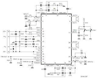
Stereo Power Amplifier is 2x70Watt STA550 chip audio power with BASH concept that can be connected with digital perangkkat. 2x70Watt STA550 Stereo Power Amplifier is an amplifier with BTL system with symmetrical power supply with ground. Power amplifier STA550 uses power output transistor which is on the chip and is set to produce a high efficiency audio power.
Power output on the STA550 is using the system without copling ac bridge (direct) and zero offset. Strengthening of the STA550 from stereo power amplifier is +12 dB. 2x70Watt STA550 Stereo Power Amplifier is equipped with temperature sensors for protection from overheating and current-limiting protection system for power amplifier. 2x70Watt STA550 Stereo Power Amplifier is equipped with standby and mute controls to regulate silent or active mode power amplifier.
Feature Stereo Power Amplifier 2x70Watt STA550 :
Monochip Bridge Stereo Amplifier dengan Bash® Architecture55+55w Output Power @ Rl = 4/8 W, Thd = 0.5%
70+70w Output Power @ Rl = 4/8 W, Thd = 10%
High Dynamic Preamplifier Input Stages
External Programmable Feedback Type Compressors
Ac Coupled Input To Class Ab Bridge Output Amplifier
Precision Rectifiers To Drive The Digital Converter
Proportional Over Power Output Current To Limit The Digital Converter
Absolute Power Bridge Output Transistor Power Protection
Absolute Output Current Limit
Integrated Thermal Protection
Power Supply Over Voltage Protection Flexiwatt Power Package With 27 Pin
Bash® Licence Required
Tuesday, November 19, 2013
9V output switching power supply
By using the circuit you do not bother to roll up a transformer that is used to reduce voltage AC 220V to 7V ,9 V or 12V, etc. When using a large transformer we will find it hard to make transformator. by rolling hundreds or even thousands of times roll. But if you use this circuit a little just enough to roll trafo not to small, and its be relatively small.

R1________________________________680K
R2________________________________47K
R3________________________________100R
R4________________________________1K
R5________________________________1R
D1,D2,D3,D4,D7,D8,D9,D10__________1N4007
D5,D6_____________________________1N4148
C1________________________________2u2F 400V
C2________________________________2n2
C3________________________________47uF 25V
C4________________________________10n
C5________________________________470uF / 16V
Q1________________________________MJE13003
Q2________________________________S8050
This is construction of transformer. For the first toll 220 times , then after that wrap right on top of L2 , and L3 on L2.

Power Amplifier Circuit 2 x 20 W stereo with IC AN7156N
This circuit operate with IC AN7156N . You just can use this IC , because havnt similarity it. In this Circuit have 2 input IN R and IN L and have Output R and L . Voltage supply require 15 V , minimum voltage 9 V and maximum voltage 24V . And the voltage must DC voltage , and better the DC voltage filtering .
Maximum Output for 1 speaker 25 W , so this circuit have maximum output 2 X 25 W with minimum impedance 4 ohm. See this circuit schematic below :
 |
| Click image to view enlarge |
Car Amplifier with IC LA4445
This circuit using IC LA4445 , this is stereo amplifier with power output 2 X 18 Watt, with this circuit you can use to car amplifier or to other elctronics device. Speaker use woofer with impedance 4 Ohm with power up to 20 Watt. Minimum voltagte require 10 Volt and maximum voltage 18 volt.see schematic below :

If you cant operate the circuit , please check IC , and then voltage in. If voltage is good check the component are. If components are working . Please check speakers.
2 Way Speaker Crossover circuit

The series of crossover is an electronic circuit in which the point to separate the audio sound frequency. objective that only sound with a frequency range that can be accepted speakers are forwarded. less is more like a filter function, so the speakers work optimally.
2 way or 3 way or else, that determines how many channels would be separated voice. Each channel is handled by a single class of speakers. Eg 3 way, the frequency of sound produced by the head unit, separated by crossover as a low freq (big size distinguished speaker better known as the subwoofer), medium freq (medium speakers), usually in the middle) and hi freq (small speakers I would call a tweeter) Let me better sound and reduce noise.
2 way or 3 way or else, that determines how many channels would be separated voice. Each channel is handled by a single class of speakers. Eg 3 way, the frequency of sound produced by the head unit, separated by crossover as a low freq (big size distinguished speaker better known as the subwoofer), medium freq (medium speakers), usually in the middle) and hi freq (small speakers I would call a tweeter) Let me better sound and reduce noise.
 |
| Schematic 2 Way Speaker Crossover |
Monday, November 18, 2013
Main function of TV tuner
 The main function of the tuner is to select the RF signals from the desired frequency spectrum wave on VHF and UHF and more signs in the air Changing RF variable into a fixed IF frequency and to provide sufficient strengthening to cover the original data that has been transmitted.
Block diagram of a series of TV tuner to receive the frequency VHF / UHF

Operational Tuner [Theoretical]
Tuner is controlled by a microprocessor in the TV chassis, which functions to receive / select a frequency. Exchange of information is channeled through the terminal Address, Clock and Data.
In the tuner, there are ICs that function to translate the instruction / data so that the tuner can function to select the desired frequency. The IC consists of some combination of series, including PLL, Local Oscillator [VCO], Mixer and IF amplifier. Everything artifacts in one chip / one chip. For further analysis, CXA3135 IC with I2C format will be taken as an example.
DC DC Converter 12V to 24V
This simple circuit is a DC-DC converter that converting up 12V source to a 24V. It can be used to run radios, small lights, relays, horns and other 24V accessories from a 12V vehicle with a maximum draw of about 800mA.
This DC-DC Converter can be used to charge one 12V battery from another, or step up the voltage just enough to provide necessary overhead for a 12V linear regulator. Using one op-amp as a squarewave oscillator to ring an inductor and another op-amp in a feedback loop, it wont drift around under varying loads, providing a stable 24V source for many applications. With a wide adjustment in output this circuit has many uses.
Parts List
R1-R4,R7-R8 100K 1/4W Resistor
R5 470 Ohm 1/2W Resistor
R6 10K Linear Pot
C1 0.01uF Mylar Capacitor
C2 0.1uF Ceramic Disc Capacitor
C3 470uF 63V Electrolytic Capacitor
D1 1N4004 Rectifier Diode
D2 BY229-400 Fast Recovery Diode See Notes
Q1 BC337 NPN Power Transistor
U1 LM358 Dual Op Amp IC
L1 See Notes
MISC Board, Wire, Socket For U1, Case, Knob For R6, Heatsink for Q1
DC- DC Converter Notes
1. R6 sets the output voltage. This can be calculated by Vout = 12 x (R8/(R8+R7)) x (R6B/R6A).
2. L1 is made by winding 60 turns of 0.63MM magnet wire on a toroidial core measuring 15MM (OD) by 8MM (ID) by 6MM (H).
3. D2 can be any fast recovery diode rated at greater then 100V at 5A. It is very important that the diode be fast recovery and not a standard rectifier. 4. Q1 will need a heatsink.
12V to 30V DC to DC Converter Schematic
12V to +/- 30V DC to DC Converter Circuit Diagram

This is a DC to DC converter for car power amplifier. 12V input generates +30V and -30V output for preamp or power amplifiers. Circuit uses SG3525 IC, Mosfets and switching power supply.
Power amplifier compatible with TV audio

In this amplifier circuit using IC TDA8944J as the main amplifier with dual-channel audio amplifier with 2 x 7W output power at 8 Ω impedance. And a minimum supply voltage of 9-18 Volts. In this ic contains two Bridge Tied Load or BTL amplifier.
The circuit is often found in audio amplifier in a series of television, besides TDA2003, TDA2006 and so forth. PCB for a series of amplifiers using IC TDA8944J is very compatible with all other types of IC in IC TDA894X family unit , and below is a schematics.

Sunday, November 17, 2013
Converter with 2N3055 transistors
This plain converter using a Zener diode and a transistor into a 9V DC 12V DC battery power to the most 1A. The circuit is very simple to build, and requires just 3 electronic components, resistors, zener diodes and transistors. The 2N3055 transistors, 1N4738A Zener diode before Zener voltage and the same power. 3W, and perhaps wire wound resistor 3R type. Powering a expedient tool to avail yourself of 9V DC.
 |
| Converter with 2N3055 transistors |
The output voltage of the following formula:
Zener voltage Vout = + 0.65V, 0.65V, which is the heart-emitter voltage of transistors
4 20 Volts Amplifier Circuit
This is an audio amplifier circuit based on IC, and IC were used that MPC563 with minimal output 6W, with impedance of 4 Ohm. Supply Voltage Minimum 4 Volt DC and a maximum voltage to 20 Volts DC. See him under this Scheme.
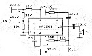 |
| 4 - 20 Volts Amplifier Circuit |
Tube Power Amplifier 35W Push Pull
Tube Power Amplifier 35W Push Pull is made using a tube and eventually compiled configuration push-pull amplifier. Tube Power Amplifier 35W Push Pull tube til it using EL-34 as the amplifier end.
In the power amplifier that is made with a tube at a glance looks simple because the use of active components that are not complex. It should be noted that the use of tubes in Tube Power Amplifier 35W Push Pull require a high voltage supply, therefore in the process of making and finishing must be careful of high voltage and radiation. Detailed series of Tube Power Amplifier 35W Push Pull can be seen in the following figure. Tube Power Amplifier Series 35W Push Pull

Sign Components Tube Power Amplifier 35W Push Pull
R1 = 470K 0.5 W
R2-5 = 2K2 0.5W
R3 = 150K 0.5W
R4 = 220K 0.5W
R6-10 = 56K 0.5W
R7 = 3.9K 0.5W
R8 = 220R 0.5W
R9 = 1M 0.5W
R11 = 39K 1W
R12-23 = 180K 0.5W
R13-21 = 820K 0.5W
R14-22 = 5K6 0.5W
R15-20 = 680K 0.5W
R16-19 = 100K 0.5W
R17-18 = 3K3 1W
R24 = 470R 2W
TR1-2 = 470R 1W Variable (adj. 270Ω)
C1-3-6-7 = 0.1uf 630V
C2 = 220pF 600v
C4-5 = 16uF 550V
C8-9 = 0.1uF 630V
C10-14 = 0.47uF 630V
C11-13 = 25uF 40V
V1 = E80CC
V2 = E80CC
V3-4 = EL34
Rectifier tube = Z2C
Audio Transformer for T1 = 2x EL34 Push Pull
Power amplifier with tubes often become the choice for a small slewrate so that the resulting audio quality is guaranteed. Tube Power Amplifier 35W in the circuit that is required to supply a high DC voltage is +220 VDC ddengan order to work properly.
Car amplifier circuit with IC BA532
Minimum Voltage required for this circuit 6 volt and maximum voltage 18 volt . Its can use to amplifier on the electronic devices such us Radio , DVD , MP4 , MP5 , and etc. To amplify the signal sound to audio sound , If you want to bring amplfier you can use the 6V rechargeable battery is able to turn it. What use the rechargeable battery ? because with rechargeable battery when battery runs out , you can charge back.
See Amplifier schematic with IC BA511 below :
 |
| Click to view large |
Maximum output power 10 Watt with impedance 4 ohm. The circuit is mono amplifier. You can use the circuit to car amplifier because support to low power subwoofer speaker
Saturday, November 16, 2013
RF AF signal detector

The series that we will make this is a special electronic circuit can be used to detect the presence or absence of signal AF / RF. The circuit is very neat and simple to make. Costs it takes quite cheap. If you are already assembling this circuit, then with easy reader determine whether there is AF or RF signal at a particular section of a circuit.
Basic circuit uses an audio amplifier and a loudspeaker with switch input for AF and RF signals. The whole device can be made small as possible so it can be included in a container to maintain security. Audio amplifier section in this series created by IC TDA 2822M, with low stereo power amplifier in 8-pin mini-DIP. IC is used as a bridge cofiguration to shrink to 250 mW output power, loudspeaker handle 4 ohm, 500mW. The current required is less than 10mA with voltage of 3V battery.
 |
| RF-AF signal detector schematics |
How it Works circuit
When the selector switch in the AF position, working on the input audio signal AF amplifier input (pin 7 of IC 1) through a capacitor C2 and potentiometer VR1. Capacitors C2 always hold input amplifier of the DC voltage and make it happen in the audio signal frequency. Input Signal IC 1 can be arranged with the help of potentiometers VR1.
When the selector switch in position RF and demodulator detector circuit formed by capacitor C1, diode D1, and resistors R1 and R2 are connected to the input The set. When the audio signal is detected then it will actually go kerangkaian to be strengthened. Signal detection is done by plugging probe (probe) on the legs of the existing components.
Fan control temperature using sensor LM35

Basic circuit of the LM35 are made to control the fan is either used on amplifier that requires automatic cooling. Its use on power amplifier circuit above and only requires DC fan. From basic sensors based on ic and amplifier op-amp is added again to the transistor Q1 to drive the fan.
Part List :
R1___220K
R2___100K
R3___3K3
R4___22K
R5___1M
R6___150R
R7___2K2
R8___33R 4W
C1___100pF
D1___1N4148
IC1__7915
IC2__TL072
IC3__LM35
F1___DC Fan 12V
Tri Waveform Generator
The Tri-Waveform Generator can be used for a number of different uses. The one that I use it for is a signal generator to test circuits. The frequency range is 20 to 20khz. and can be adjusted by R1. The duty cycle or the time that the waveform is high and the time that the waveform is low can be adjusted by R4. The purpose of R2 and R3 are to clean up any distortion on the sine wave output. To do this you must hook up the sine wave output to and oscilloscope and adjust R2 & R3 to make the sine wave as accurate as possible.
Tri-Waveform Generator Circuit Diagram

Tri-Waveform Generator Circuit Diagram
L6203 DC Motor Controller
This DC motor controller circuit shown in this schematic use the L620x motor driver . The L620x is a monolithic full bridge switching motor driver realized in the new Multipower-BCD technology which allows the integration of multiple, isolated DMOS power transistors plus mixed CMOS/bipolar control circuits and is available in many versions : L6201 /1PS/2/3 .
L6203 DC Motor Controller Schematic

All this motor driver circuits are identically , the differences between them is the total RMS current , which is up to : 1A for L6201 , 2A for L6202 and 4A for L6203 and L6201PS . If the device is combined with a current regulator like the L6506 , can be implemented a transconductance amplifier for speed control, as shown in this circuit schematic . In this configuration only half of the L6506 is used and the other half of the device may be used to control a second motor.
The L6506 senses the voltage across the sense resistor RS to monitor the motor current: it compares the sensed voltage both to control the speed and during the brake of the motor. A snubber network made by the series of R and C must be foreseen very near to the output pins of the I.C.
The following formulas can be used to calculate the snubber values:
R @ VS/lp ; C = lp/(dV/dt) where:
VS is the maximum Supply Voltage foreseen on the application; Ip is the peak of the load current; dv/dt is the limited rise time of the output voltage (200V/ms is generally used).
of the IC. Sometimes a capacitor at pin 17 of the L6506 let the application better work.
L6203 DC Motor Controller Schematic
The L6506 senses the voltage across the sense resistor RS to monitor the motor current: it compares the sensed voltage both to control the speed and during the brake of the motor. A snubber network made by the series of R and C must be foreseen very near to the output pins of the I.C.
The following formulas can be used to calculate the snubber values:
R @ VS/lp ; C = lp/(dV/dt) where:
VS is the maximum Supply Voltage foreseen on the application; Ip is the peak of the load current; dv/dt is the limited rise time of the output voltage (200V/ms is generally used).
of the IC. Sometimes a capacitor at pin 17 of the L6506 let the application better work.
Friday, November 15, 2013
Transistor Checker with 555 Timer 4027IC
This regular circuit has helped me prohibited on many occasions. It is able to check transistors, inside the circuit, down to 40 ohms across the radio dish-foot otherwise base-emitter junctions. It can in addition check the output power transistors on amplifier circuits. Circuit company is because follows. The 555 timer ( IC1 ) is usual up as a 12hz multi vibrator. The output on pin 3 drives the 4027 flip-dud ( IC2). This flip-flop divides the input frequency by two and delivers complementary voltage outputs to pin 15 and 14. The outputs are connected to LED1 and LED2 through the current limiting resistor R3.

The LEDs are arranged so to facilitate what time the polarity across the circuit is lone way single one LED force light and what time the polarity reverses the other LED will light, therefore while rebuff transistor is connected to the tester the LEDs will alternately flicker. The IC2 outputs are too connected to resistors R4 and R5 with the junction of these two resistors connected to the immoral of the transistor being tested. With a proficient transistor connected to the tester, the transistor yearn for circle on and crop a passing across the LED duo. If a good NPN transistor is connected next LED1 will burst by itself and if a good PNP transistor is connected then LED2 will flash by itself. If the transistor is initiate both LEDs force flash and if the transistor is shorted at that moment neither LED will flash.
Accu charger use a diac and triac
This circuit can be used to charge Accu and cells battery , the circuit can has a very stable output that would make the battery last longer and maximize the added battery capacity. When charge was also quite fast , so it can optimize the time.

A diac is used in the gate circuit to provide a threshold level for firing the triac . C3 and R4 provide a transient suppression network. R1 , R2 , R3 , C1 , and C2 provide a hase - shift network for the signal being applied to the gate. R1 is selected to limit the maximum charging current at full rotation of R2.
IC Amplifier with HA13118
IC amplifier 18 watt circuit is an IC digit HA13118 Hitachi powerfully. with the intention of the IC yearn for take place integrated amplifiers, categorize AB. And this cycle is to assistance a association circuit. to the same degree a answer, growth toll up to 55 dB. And pressure from 8-18 volt the current 1-2 amps, with not as much of than 0.2% distortion by 1W. And response. frequencies from 30 Hz-30 kHz.
 |
| IC Amplifier with HA13118 Circuit Diagram |
As entering the power supply circuit, and paid into the audio input. The audio is through VR1 adjusts the level of the audio sign. And pass the C1 coupling signal. The C2 eliminate the interference. From the audio signal to come to pass sent through to the input pin on pin 3 of IC1. so as to this circuit to circuit modish the form of conduit circuits otherwise expansion of the not here navigation. And restore channels laid back, to follow a elevated watt power. The observations from the pin 15 which is the output of absent channel speakers are connected to individual fringe. And the other side of the speakers are connected to the output of pin 8, which is the output of the right. The C7 and C8 acting reaction hint to the circuit’s frequency response is better. The C9, C10, R1 and R2 willpower wait on unconcerned the campaign. And C11, C12 serve to filter the light as it should be to prevent several din shock.
IC LA78040 schematic for vertical deflection
Synchronization circuit to make the signals useful in the process of scanning of the transmitter and sent to the Vertical and Horizontal. To be able to produce images on the picture tube phosphor surface is the same as what was sent, then the necessary adjustments to correct with ualsan which has decomposed on the sender and receiver on the review must be made again, and this is called synchronization.
 |
| Click to view larger |
On TV transmitter switching pulses that have made the same frequency as in the reviewing, and by using the switching pulse is then mulapenguilasan point getter on the tube and picture tube can be adjusted simultaneously.
At the transmitter, each end of the line reviews one pulse is emitted horizontally, and also at each end of the line vertical review (this is called a field review), another pulse is emitted. At the receiver using switching pulses had the time of the beginning (start) review can be arranged horizontally and vertically. Switching pulses are called the horizontal synchronizing signal and vertical synchronization. Vertical Synchronization A. Vertical in the tv series has the following functions a) bend / open beams of light (information) to the vertical direction. b) Synchronize files from a transmitter in the form of images with short time.
Thursday, November 14, 2013
Basic Home Theater Design
 |
| Basic Home Theater Design |
Folks continually long for to bring native land a quantity of luxurious home entertainment scheme. This is for the reason that solitary very the minority households can afford home the stage system. Of postponed, only the rich and the famous can afford such luxury. This notion is at this point a point of the onwards. Home plays systems may perhaps now transpire free to greater run to of households as of the comprehension of necessary home the stage design. The basic home theater design possibly will merely require three basic components and these three components might already be present reasonable meant for the working group of pupils.
However, prior to you may possibly need to think of the essential in drama design for your home theater orderliness, you may perhaps need to know the size of the area for the home the stage align up. The size of the area to somewhere the home show business willpower be there set up will depend on how prime the home drama design needs to be.
Home theater experts recommends with the aim of if the span is quite unimportant, all you need used for your home plays design is a television set, three speakers and a DVD player. The home plays design may well be located dependent of the shpre of the span; however, the spot of the speakers remains to be the missing, the in shape and the focal point of the space. central homespun plays design may perhaps require a television set better than 27 inches. Too diminutive screen designed for your home drama design might not be alive sufficient for a film show business-like experience. This is since even for the home drama design, you possibly will need to consider the sight and sound of a film plays. It is the foremost consideration why colonize move on to a show show business, the enormous screen and the surround sound. With respect to the surround sound of a motion picture acting, the crucial three speakers is lone applicable pro lesser temporary housing, if the extent is superior, the place of origin show business design needs to be situated new than three, you may well go up to six speakers and a complimenting subwoofer may be de rigueur for the surround effect. up for grabs back to a undersized scope, if you hope against hope individual locate three speakers, you can require to consider wholesale a soaring quality brand amp; this will give away you an adequate amount of surround sound in place of a lesser opportunity.
If you own a miniature funds, ensure to facilitate the pile up wherever you spirit purchase your speakers will allow you to test the merchandise happening your extent and if it will not give you a first-rate surround sound, they be supposed to allow you to return otherwise change the item. This is as certain speakers sound good in the store but while you conclusively established them up in a tiny space, the effect is not very good. hit upon a neat deal somewhere they can allow you to return before use instead the speakers. However, if your resources is sufficient, you can consider hiring the services of a domestic the stage designer. Your home theater designer determination stay able to design the home the stage better and with complete accessories. He can require examination the power rating, and the need pro amplifiers. He may perhaps moreover vouch for using home plays projectors and he may recommend how the speakers need to be present. You preference develop a obedient home plays design if you will be able to hire home show business designers. The need designed for home theater sitting room and television cabinet may perhaps too be basic for the complete package of your home plays.
You might get pleasure from the entertainment devoid of having to tide traffic jam and enjoy inwards your own to your place the stage organization.
Class A headphone amplifier
Class A headphone amplifier
 |
| Class A headphone amplifier |
Digital visitor counter
Digital visitor counter is a reliable circuit that takes over the task of counting Number of Persons/ Visitors in the Room very Accurately. When somebody enters into the Room then the Counter is Incremented by one and when any one leaves the room then the Counter is Decremented by One. The total number of Persons inside the Room is displayed on the seven segment displays. The microcontroller do the above job it receives the signals from the sensors, and this signals operated under the control of software which is stored in ROM.
 |
| Digital visitor counter |
 |
| Digital visitor counter |
Arrow LED Indicator using 74hc14 IC
This arrow led indicator electronic project can be used in some dark places to show the directions . You can use to indicate direction just an illuminated arrow or a flashing light , but is much nicer if the light moves in the correct direction.
This arrow led indicator is based on 74HC14 circuit and some LEDs which are used to show the way .
For this arrow led indicator we need six series of three LEDs arranged in the shape of arrows and are connected to the outputs . Each time the lit arrows move over by one column so it appears that the arrows run from right to left.
Arrow LED Indicator Circuit Diagram

If we want to change the speed of the moving light it’s need to change the value of C1 to C3 or R1 to R3 ( a lower value for this components decrease the time of moving lights). If we want a longer arrow we can mount in parallel with existing columns another columns .
For power supply we can use batteries or 6V regulated power supply .
This arrow led indicator is based on 74HC14 circuit and some LEDs which are used to show the way .
For this arrow led indicator we need six series of three LEDs arranged in the shape of arrows and are connected to the outputs . Each time the lit arrows move over by one column so it appears that the arrows run from right to left.
Arrow LED Indicator Circuit Diagram
If we want to change the speed of the moving light it’s need to change the value of C1 to C3 or R1 to R3 ( a lower value for this components decrease the time of moving lights). If we want a longer arrow we can mount in parallel with existing columns another columns .
For power supply we can use batteries or 6V regulated power supply .
Wednesday, November 13, 2013
Video Amplifier Circuit Diagram
Video amplifier circuit is simple and can be used. Video amplifier circuit was constructed from 2 pieces of transistors BC550 and BC560. The source voltage used for supplying the video amplifier circuit is 5VDC. Video amplifier circuit is equipped with a powerful regulator which flows through both transistors T1 and T2, the components used to manage these flows are P1 and P2.
 |
| Video Amplifier Circuit Diagrams |
Then the video amplifier circuit is also equipped with limiting the maximum current that passes through T1 and T2. The components in black block functions as limiting the maximum current that is passed by the T1 and T2 for no more than 5mA.
AT89C2051 microcontroller circuit
Real time controller AT89C2051
Real time controller is a device used to exercise control over household device continuously ongoing and scheduled. The series of Real Time Controllers with microcontroller AT89C2051 which dituls in this article is a tool that can do that serve targeted. The series of Real Time Controller with Microcontroller AT89C2051 Atmel AT89C2051 uses a data processor and controller as device installed.
In the application directly devices requires a separate interface from a wide range of Real Time Controllers with this AT89C2051 microcontroller. When will connect the device with the AC power source to use interface optocoupler (MOC) or solid state relay. Devices that can be connected with the series of Real Time Controller with Microcontroller AT89C2051 include lights, water machines, fans, electronic gate. The series of Real Time Controllers with this AT89C2051 microcontroller to control a height of water level, controlling the flame lights the scheduled SCARA and censored.

Specifications Series Real Time Controller with AT89C2051 Microcontroller
The series of Real Time Controller with Microcontroller AT89C2051 uses a computer to perform serial communication settings via computer. The series of Real Time Controller with Microcontroller AT89C2051 has 6 units of output channels that can be independently controlled depending on the program induced in the tool. Output in the series of Real Time Controller with AT89C2051 microcontroller requires an interface to deal with equipment that will be in control.
Power Supply with regulator output use IC uA723
This circuit operating with IC uA723 and add amplified with transistor TIP31 or similiar transistor with TIP31 . Input voltage for circuit about 10 - 40 volt DC , formerly of AC voltage 220 volts or 110 volts , then lowered by the transformer voltage to 30 volts. And the supply output voltage from 1 volt to 35 volt DC you can adjust it on potentiometer R2.
See this circuit power supply below :

Output voltage transformer used 10 to 40 Volts . On resistor Rsc is the current limit set resistor. Its value is calculated as :
Rsc = 0.65 Volt For Example : If you need current output 2.0 A
Rsc = 0.65 / 2.0 = 0.32 Ohm So , you must use 0.32 Ohm to current output 2.0 A
140W audio amplifier with IC STK070
By using the above amplifier circuit you can hear the sound quality is quite good by a high output power. Maximum voltage circuit pa approximately 55Volt DC. 70-140W output power with impedance 8Ohm.

Part List
R1 = 10K
R2 = 1K
R3 = 0.4R
R4 = 0.4R
R5 = 4.7R
C1 = 0.015
C2 = 10uF
C3 = 220uF
C4 = 0.15uF
C5 = 220uF
C6 = 47uF
C7 = 0.047uF
U1 = STK050 , STK070
Tuesday, November 12, 2013
Schematic Audio Amplifier with IC AN374
This Schematic use IC AN374, this is mono amplifier and have output speaker 1 W with impedance 8 Ohm . Supply need 8Volt to 16 Volt , this Schematic you can use current Voltage 12 V. And better use the stabilizer with 7812 let the voltage stabil. The Effect will be on the sound so smooth.
See this Schematic below and see datasheet IC AN734 :

Datasheet IC AN374
Vcc = 8-16 V
Pout = 1 W
RL = 8 Ohm
Ft = 50hz - 17Khz
Icco = 12 mA
Package = SIP2-10
Manufactered = MATSUSHITA
Sound Signal Processor with MSP 34X0G

IC MSP 34X0G is a single chip that can process voice signals to all TV standard International, and very good for the digital NICAM stereo. In the IC has several advantages, namely:
- Communication using the I2C bus control
- Selection of a voice signal automatically (mono / stereo / bilingual)
- Loudspeaker / headphones are equipped with volume control, bass, treble, loudness and balance
- Loudspeaker outputs are equipped with MDB (Micronas Dynamic Bass)
- AVC: Automatic Volume Correction
- Equipped with Sub woofer output
- Have facilities 5-Band graphic equalizer for loudspeaker
- Equipped spatial effect for loudspeaker
- Equipped with a matrix of voters in / out
- Has a SCART 4 stereo inputs, one mono input and 2 stereo SCART output
 |
| Block diagram of circuit in the IC MSP34X0G |
PWM controller with 555 timer chip

IC Timer 555 has a basic PWM controller with pulse width control feature 0 .. 100% which is controlled using the R1, at the time of controlling the oscillator frequency relatively stabi so it may be used to build the Simple PWM controller.
Frequency of Simple PWM controller 555 depending on the value of R1 and C1, values shown R1 and C1 will form the output with a frequency of 170 to 200 Hz. Diode-diode used in the Simple PWM controller With this 555 can use a 1N4148.
R2, R3 and C3 form a giver triger circuit beginning at the reset IC 555 for 2 seconds. If you want to use a series of Simple PWM controller 555 with the V + not +12 V, it does not matter to raise tilapia R2 where (V + * R2) / (R2 + R3) is about 2, because it limits the signal level reset is 0.5 .. 1V. If you do not do that, then signal the kickstart to get too close to the limit reset signal reception.
 |
| PWM controller circuit |
Q output of 555 on the Simple PWM controller circuit 555 is used for driver PWM pulse, so that the discharge pin is used for transistor output driver instead. This is an open collector output, and is used as an active signal is low, so it can work. D3 protects the output transistor of the load induction. You may replace any suitable transistors for Q1, BD140 is 1.5 amps.
C4 and C5 is the power decoupling capacitor for the IC 555 on the Simple PWM controller circuit 555, which produce relatively large level of push-pull output stage.
Subscribe to:
Posts (Atom)