Thursday, October 31, 2013
High power car audio amplifier
 This is a power amplifier which functioned as the car audio amplifier IC that uses PA02 and LH0101. That each IC has a 30W output power with 8 ohm impedance.
Part List
R1 = 10K
R2 = 0.15R
R3 = 20K
R4 = 2.7R 1W
R6 = 15R
R7 = 10K
C1 = 0.1uF
C2 = 0.1uFC3 = 0.1uF
IC = LH0101 , PA02

Supply voltage from 7 volts to 25 volts. For a car battery can also be used but must be first converted into voltage +, -, and ground. Following a series of amplifier.
Telephone Headgear Circuit Diagram
Acompact, inexpensive and low component count telecom head- set can be constructed using two readily available transistors and a few other electronic components. This circuit is very useful for hands-free operation of EPABX and pager communication. Since the circuit draws very little current, it is ideal for parallel operation with electronic telephone set.
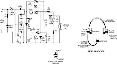
Working of the circuit is simple and straightforward. Resistor R1 and an ordinary neon glow- lamp forms a complete visual ringer circuit. This simple arrangement does not require a DC blocking capacitor because, under idle conditions, the telephone line voltage is insufficient to ionise the neon gas and thus the lamp does not light. Only when the ring signal is being received, it flashes at the ringing rate to indicate an incoming call. The bridge rectifier using diodes D1 through D4 acts as a polarity guard which protects the electronic circuit from any changes in the telephone line polarity.
Zener diode D5 at the output of this bridge rectifier is used for additional circuit protection. Section comprising transistor T1, resistors R2, R3 and zener diode D6 forms a constant voltage regulator that provides a low voltage output of about 5 volts. Dial tone and speech signals from exchange are coupled to the receiving sound amplifier stage built around transistors T2 and related parts, i.e. resistors R7, R6 and capacitor C5. Amplified signals from collector of transistor T2 are connected to dynamic receiver RT-200 (used as earpiece) via capacitor C7. A condenser microphone, connected as shown in the circuit, is used as transmitter. Audio signals developed across the microphone are coupled to the base of transistor T1 via capacitor C3. Resistor R4 determines the DC bias required for the microphone. After amplification by transistor T1, the audio signals are coupled to the telephone lines via the diode bridge. The whole circuit can be wired on a very small PCB and housed in a medium size headphone, as shown in the illustration. For better results at low line currents, value of resistor R2 may be reduced after testing
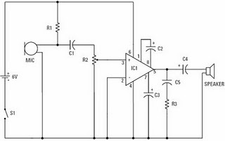
Schematic Audio Power Amplifier with IC AN7120
This schematic use the IC AN7120 for main system power amplifier with support some other components. In this circuit have a good sound quality. Because output noise is very very minimal , not even be heard in the distance of 5 Cm from the sound. Description from this circuit , voltage minimum required 6 volt and maximum voltage 20 volt , you can choose voltage between it. Maximum output Power 15 Watt with impedance 4 Ohm.
See Schematic Power Amplifier below :
 |
| (Figure 1.0) Schematic Circuit Power Amplifier AN7120 |
Auto Sound Systems are more than meets the Eye
The auto sound systems of today are much more involved and complicated than the simple car stereo and speakers of years long past. Todays sound systems have all kinds of bells and whistles that many us could have only imagined during our younger years. In fact, it is quite possible that many of us did imagine these and those imaginings are how they came to be. One thing you need to do before you even begin to put the auto sound system of your dreams together is learn what kinds of components exist, how they work together, and which ones you really think you need as part of your auto sound system and which components you honestly feel you can live without.
Life is about compromise and most of us will readily admit that we are quite unlikely to ever use all the bells, whistles, and upgrades that are made available to us within our lifetimes. I dont know about you, but my cell phone has features Ive never even gotten around to learning how to use. I know I can use them and I have a subscription to do so, but have never managed to actually get around to watching the news, I find that if I am on my phone the news would be an interruption and if I am in the mood to watch the news, Ill generally find a television and watch on a larger screen.
Our auto sound systems are a lot like this. If you dont do an extensive amount of travel with little ones in your car, it is unlikely that you will need a sound system that allows wireless speakers for the back seat. However if you are putting a good sound system in your family car, this may be a good idea, as we dont always enjoy the same music as our children. I dont know about you, but I can only handle "The Wheels on the Bus" so many times in one car trip. For that reason alone I think the individual headphones are a wonderful idea.
One thing that I have found I cant live without in my auto sound system is an MP3 player. Im literally addicted to audio books and have found that I can subscribe to an online service that allows me to download entire books to my computer and either burn them to a CD or put them on a memory stick to play on my next road trip. It makes the trip seem to go so much more quickly when I have something to occupy my mind rather than switching radio stations on a regular basis in search of a song I enjoy that hasnt been overplayed.
Some people cant live without at least a 6-disc CD changer as part of their auto sound system and others find that XML is the only way to go. Whatever your choice, the thing to remember is that it is your choice. Only you can choose the auto sound system that works best with your tastes and requirements. Only you can decide whether or not you enjoy the sound your sound system provides, and only you can decide which bells and whistles are important and essential and which ones you can live without. It is your money that will pay for the upgrades you desire and your tastes they should please.
Take the time to study not only the music, but also the sound and the components that are available for the sound system you choose. Also pay close attention to what is included in the price you think you are paying. More often than not each component is sold as either an add on or an upgrade so be careful that you arent getting less than you think you are or paying more than you think you will be paying for the auto sound system you choose.
Wednesday, October 30, 2013
100W with PCB Power Amplifier Circuit
 |
| High Power Amplifier |
Technical Specifications - Characteristics 100W Power Amplifier :
Output power (f=1 KHz, d=0.5 %): 100 W in 8 ohm
Supply voltage: ................ с 40 V
Quiescent current: ............. 50 mA
Maximum current: ............... 2.6 A
Sensitivity: . 600 mV
Frequency response: ............ 10-35000 Hz (-1 dB)
Distortion HD: ................. 0.01 %
Intermodulation dist.: ......... 0.02 %
Signal/noise: 83 dBConstruction
100W Power Amplifier Circuit Diagram :


L1 : 10 turns with wire 0,5mm turned on a restistor of 1W
If you use a 4Ohm speaker you will place R3,4,17,23 at the board
If you use a 8Ohm speaker you will place D7 D8 and R28.
For R2 and R16 if you dont find a 0,47Ohm place two of 1 Ohm parallel.
R16 must be 0,47Ohm...the 1Ohm must be a typographical error, take care of this, i havent tested it.
Printed Circuit Board 100W Power Amplifier PCB:


If it does not work :
Check your work for possible dry joints, bridges across adjacent tracks or soldering flux residues that usually cause problems. Check again all the external connections to and from the circuit to see if there is a mistake there.
- See that there are no components missing or inserted in the wrong places.
- Make sure that all the polarised components have been soldered the right way round. - Make sure the supply has the correct voltage and is connected the right way round to your circuit.
- Check your project for faulty or damaged components. If everything checks and your project still fails to work, please contact your retailer and the Smart Kit Service will repair it for you.
source:100W Audio Amplifier
Circuit Audio Amplifer with IC 5G37
Himm.,.,. I just get this schematic on my mind . This Circuit require voltage supply minimum voltage is 6 Volt and maximum voltage is 12 V . You can use voltage betwen 6 - 12 volt. Output speaker is mono with power 0,7 watt and impedance 8 Ohm.
See below this Circuit and datasheet IC 5G37 :
Datasheet IC 5G37
Vcc = 6-12 V
Pout = 0,7 W
RL = 8 Ohm
Ft = 40-17 Khz
Icco = 20 mA
Package = TABS1-14
Manufactered = China
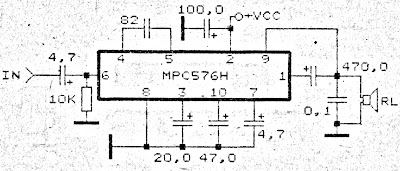
Good Quality Sound Amplifier Circuit
This amplifier circuit has a pretty good quality. Of course the sound quality, although this one amplifier does not have a large output power but in terms of soft and loud voice that this amplifier can be unreliable.
With a single IC capitalize MPC576H and several other supporting components you have to make this amplifier circuit. Voltage at least 9 Volt and 24 Volt Max. Output Power 3.5 Watts with 8 Ohm impedance.
With a single IC capitalize MPC576H and several other supporting components you have to make this amplifier circuit. Voltage at least 9 Volt and 24 Volt Max. Output Power 3.5 Watts with 8 Ohm impedance.
 |
| Good Quality Sound Amplifier Circuit |
Remote Solar LED Light
I created this circuit in an attempt to make the simplest possible solar powered project. It would make for an excellent science fair project, and would also serve as a good introduction to solar powered circuitry. It may also have some practical uses, such as shedding some light into a dark part of your house. The idea is simple, the solar panel converts sunlight into a trickle of electricity. The electricity is used to run a white LED.
Remote Solar LED Light Circuit Diagram

Specifications:
The remote solar powered LED light takes advantage of the current limited nature of solar photovoltaic cells. If light shines on the solar array, current will flow through the circuit. For a typical size of solar cell, there is a maximum current that can be produced. The maximum solar cell current is simply matched to a value of current that the LED can handle. If there is enough light to raise the solar panels voltage above around 3.7V, the white LED will light up. The LED regulates the maximum voltage across the circuit to around 3.7V.If the solar panel that you use produces more than 20ma, it may be necessary to insert a series resistor between the LED and the solar panel to prevent the LED from burning out.
A 50 ohm 1/4 watt resistor is probably about right for the job, the exact value may need to be optimized according to the solar panel that you use.This concept could easily be expanded to systems with larger arrays of solar cells and more LEDs. The capacitor is not required, but it will keep the LED from flickering if the panel is briefly blocked, such as when a bird flies by. With 7 solar cells, the LED will only light in fairly bright light, if you use up to 10 solar cells, the circuit will work nicely in overcast skies.For an interesting modification to this circuit, replace the 1000uF capacitor with a 1 Farad/5.5V "Memory Backup Capacitor". An Elna DB-545D105 device was tested on the circuit, after charging up in the sun for a few minutes, the capacitor was able to light the LED for several minutes.

Construction:
Most of the work goes into making the solar panel. Lay out the cells in any pattern. Cut the two pieces of plexiglass and one piece of perforated circuit board so that they are wider than the solar array. Stack the three board layers together and drill holes for the mounting screws. When the project is finished, the center circuit board will be spaced away from the front and back plastic panels with extra nuts acting as spacers on the mounting screws. The idea is to get an air gap above and below the circuit board so that there is room for the solar cells and wiring.
Mount the solar cells on the perf board and solder them into a series string. An easy way to do this is to connect short segments of bare wire-wrap wire to each cell, route the wires through the perf board and solder the ends on the bottom. Connect two wires to the ends of the series string of cells and secure the wires to the circuit board. For outdoor applications, seal the edge of the panel with silicone caulk or other water proof material. Also, seal the mounting screws where they pass through the plexiglass.Connect the LED and capacitor in parallel, wire them across the two power leads. Be sure to get the polarity correct, otherwise the LED wont light up. Solder the parts together. Be sure to heat-sink the LED leads while soldering, LEDs can be easily destroyed with too much heat.
Use:
Place the solar panel in the sun, the LED will light. The photo at the top of this page shows the circuit operating indoors on a cloudy day. If you put the LED on a long wire, it can be placed in a dark location, such as a corner of your basement. As long as there is a fair amount of light in the sky, the LED will light up. To get the best orientation for the panel, aim it directly at the sun at noon during March or September.
Parts:
7-10x photovoltaic cells, rated at 15-25ma each.
1x white LED, high efficiency types work best.
1x 1000uF 15V (or greater) electrolytic capacitor.
1 piece of perforated or printed circuit board.
2 pieces of clear plexiglass.
28 gauge bare wire-wrap wire.
24 gauge speaker wire.
miscellaneous screws, nuts, and washers.
silicone caulk.
Remote Solar LED Light Circuit Diagram
Specifications:
- Operating Voltage: 3.7V DC
- Solar Current: 25ma max.
- LED Lamp Operating Current: 10-25ma.
The remote solar powered LED light takes advantage of the current limited nature of solar photovoltaic cells. If light shines on the solar array, current will flow through the circuit. For a typical size of solar cell, there is a maximum current that can be produced. The maximum solar cell current is simply matched to a value of current that the LED can handle. If there is enough light to raise the solar panels voltage above around 3.7V, the white LED will light up. The LED regulates the maximum voltage across the circuit to around 3.7V.If the solar panel that you use produces more than 20ma, it may be necessary to insert a series resistor between the LED and the solar panel to prevent the LED from burning out.
A 50 ohm 1/4 watt resistor is probably about right for the job, the exact value may need to be optimized according to the solar panel that you use.This concept could easily be expanded to systems with larger arrays of solar cells and more LEDs. The capacitor is not required, but it will keep the LED from flickering if the panel is briefly blocked, such as when a bird flies by. With 7 solar cells, the LED will only light in fairly bright light, if you use up to 10 solar cells, the circuit will work nicely in overcast skies.For an interesting modification to this circuit, replace the 1000uF capacitor with a 1 Farad/5.5V "Memory Backup Capacitor". An Elna DB-545D105 device was tested on the circuit, after charging up in the sun for a few minutes, the capacitor was able to light the LED for several minutes.
Construction:
Most of the work goes into making the solar panel. Lay out the cells in any pattern. Cut the two pieces of plexiglass and one piece of perforated circuit board so that they are wider than the solar array. Stack the three board layers together and drill holes for the mounting screws. When the project is finished, the center circuit board will be spaced away from the front and back plastic panels with extra nuts acting as spacers on the mounting screws. The idea is to get an air gap above and below the circuit board so that there is room for the solar cells and wiring.
Mount the solar cells on the perf board and solder them into a series string. An easy way to do this is to connect short segments of bare wire-wrap wire to each cell, route the wires through the perf board and solder the ends on the bottom. Connect two wires to the ends of the series string of cells and secure the wires to the circuit board. For outdoor applications, seal the edge of the panel with silicone caulk or other water proof material. Also, seal the mounting screws where they pass through the plexiglass.Connect the LED and capacitor in parallel, wire them across the two power leads. Be sure to get the polarity correct, otherwise the LED wont light up. Solder the parts together. Be sure to heat-sink the LED leads while soldering, LEDs can be easily destroyed with too much heat.
Use:
Place the solar panel in the sun, the LED will light. The photo at the top of this page shows the circuit operating indoors on a cloudy day. If you put the LED on a long wire, it can be placed in a dark location, such as a corner of your basement. As long as there is a fair amount of light in the sky, the LED will light up. To get the best orientation for the panel, aim it directly at the sun at noon during March or September.
Parts:
7-10x photovoltaic cells, rated at 15-25ma each.
1x white LED, high efficiency types work best.
1x 1000uF 15V (or greater) electrolytic capacitor.
1 piece of perforated or printed circuit board.
2 pieces of clear plexiglass.
28 gauge bare wire-wrap wire.
24 gauge speaker wire.
miscellaneous screws, nuts, and washers.
silicone caulk.
Tuesday, October 29, 2013
14 Watt car audio amplifier circuit

Basic operation of this amplifier is on IC TEA2021 ,
In this circuit minimum require voltage is 4 volts and maximum voltage 25 volts. Power output 14 Watt with 4 Ohm impedance. See this schematic.
Class A power amplifier
 Class A Power Amplifier
Examples of class A amplifier is the basic transistor circuit common emitter (CE). Amplifier type class A is made by setting dititik bias current (usually Q) on the load line. The position of point Q such a way that is right in the middle line of the load curve VCEIC from the amplifier circuit.
The is an example circuit with common emitter NPN transistor Q1.

Line load on this amplifier determined by the resistor Rc and Re from the formula VCC = VCE + ICRC + IeRe. If Ie = Ic, it can be simplified into VCC = VCE + Ic (Rc + Re). Next line load circuit can be described by a formula them. While resistors Ra and Rb were installed to determine the bias currents. Magnitude resistors Ra and Rb in related series determining how much current Ib the cut point Q. Large Ib flows usually listed on the data sheet used transistors.
Great strengthening AC signals can be calculated with an AC signal circuit analysis theory. In an AC circuit analysis of all components of the capacitor C connected brief and the imaginary connecting the VCC to ground. With In this way a series of images 1-18 can be assembled into such picture 1-20. Resistors Ra and Rc is connected to GND and all short-circuited capacitor.
Typical class A amplifier, all output signals to work on active region. Amplifier type class A is called as a reinforcement that has fidelitas a high level. Provided the signal is still working in the active region, form the output signal will exactly match the input signal. But class A amplifier has low efficiency of approximately only 25% - 50%. Its none other since the point Q is at point A, so that although there is no input signal (or when the input signal = 0 Vac) transistors to keep working in the active region with a constant bias current. Transistor is always active (ON) so that most of the sources of supply wasted power into heat. Since this is class A transistor amplifier should be augmented with extra cooling like heatsinks are more large.
KA2211 Stereo audio power amplifier
 This amplifier circuit has a stereo output with a power output of 2 x 5.8 Watt with impedance 4. The frequency response from 30Hz up to 20kHz. Amplifier circuit based on IC KA2211 and supported several other components. Minimum supply voltage of 10 Volt to 18 Volt.
Below is schematic power amplifier with IC KA2211 suitable for home power amplifier.
 |
| Home amplifier schematics with IC KA2211 |
Thermostat Circuit with IC LM56
The Thermostat Circuit IC LM56 Diagram was designed next to during kind Controller. Please examine suspiciously and discover by the side of schematic design photos of Thermostat Circuit IC LM56 Diagram to know particularize in rank.
 |
| Thermostat Circuit with IC LM56 |
Thermostat Circuit IC LM56 is especially accurate twin output abridged energy thermostat depict by citizen Semiconductors. two perpetual hotness jaunt points common at the same time as VT1 and VT2 are made with isolating the IC LM56 lone.250Volt inner voltage reference by 3 outer walls resistors (R1, R2 and R3) element. You desire discover two digital outputs on behalf of IC LM56 to is Output1 becomes Low whilst the fever increases in excess of T1 and goes extensive when the warmth decreases beneath (T1±Hysteresis warmth). Element IC LM56 has a variety of of use functions such being inner fever sensor, two inside voltage comparators, inner voltage reference and that.
Monday, October 28, 2013
Car Audio Amplifier Instalation Guide
Amplifier and speakers wiring. The amplifier does not always come with wire connection. You need a kit amp wiring harness sold separately. It is important to adjust the harness to the vehicle you have, to the right frequency and sound. The red wires (positive) is thicker than black (ground). A 12 -, 10 – or 8-gauge wire or lower is better sound quality.

Connecting the power cable and head unit. Disconnect the negative battery cable car, then the positive. Connect the red amplifier (positive) to the positive battery cable. Strip one end of the thread about half an inch and squeeze the cable connector U-Connect the positive terminal of the battery and tighten. Slide the other end through the firewall of your car, which is located towards the rear under the hood. Drag the interior and on the back of the torso. You may need to unscrew the bottom plate on each side and pull the seat back to move the thread. Black lead to an O-ring and screws for the metal of the cars to squeeze into the trunk.
Check if your head unit has suspended two AV, the ends of the women. If not, you have to buy one and have it installed. AV wire supplied with the kit must be long enough to reach from the amplifier in the trunk of the radio. Connect the ends of the red and white male to the female ends of the amplifier and the radio. Then connect the son of the subwoofer amplifier. Connect the negative terminal of the battery.
Turn the key to your car and listen to the radio at low volume. Not at full power crank. You get a distorted sound, or a speaker can blow the air. You will feel the vibration in the car audio system.
Transformer Electronics

Transformer (transformer) is the electrical / electronics that function to move energy (power) power from input to output or from the primary to the secondary side. The transfer of power from primary to secondary voltage is accompanied by changes either up or down.
There are two types of transformer Raising the voltage transformer (stepup transformers) and lowering the voltage transformer (stepdown transformer).
If the primary voltage is smaller than the secondary voltage, so-called stepup transformer. But if the primary voltage is greater than the secondary voltage, so-called stepdown transformer.At each transformer has primary windings named input and output is called the secondary winding. Has an iron core transformer for low frequency and high frequency ferrite core or some that did not have a core (air core).
When the primary winding given alternating current (AC), the primary windings will be the direction of the magnetic field also magnitnya commute. This magnetic field will induce the secondary winding and secondary winding flows resulted in an alternating current (AC). Suppose the primary coil current flows berfasa positive (+), then the current flowing in the secondary coil berfasa negative (-). Because the current through primary digulungan back and forth, then on the roll sekunderpun flowing alternating current. The amount of charge in the primary winding with the power supplied to the secondary winding. So Pp = Ps or Up.Ip = Us.Is
Where:
Pp = primary power in watts
Ps = power in watts secondary
Up = primary voltage in volts
Us = secondary voltage in volts
Ip = Primary Current in ampere
Is = secondary current in amperes
Example:
A power transformer is connected to the net voltage 220 V, current flowing in primary winding 0.2 amperes. If the secondary voltage of 12 V. Calculate the amount of secondary flow.
Completion:
Up.Ip = Us.Is 220.0,2 = 12. Is Is Is = 44/12 = 3.66 amps
Comparison of transformation:
In general, the number of primary winding is not equal to the number of secondary winding. For stepup transformer primary winding number fewer than the number of secondary winding, contrary to stepdown transformer primary winding amount more than the number of secondary winding. Number of primary winding and secondary winding number shows the amount of voltage primary and secondary tgangan magnitude. The greater the voltage the more the windings. Thus the number of winding is directly proportional to the voltage-enter the respective sides. If the secondary winding and primary winding = Ns = Np, then the ratio of primary winding and secondary winding is called the transformation ratio and expressed as T = Np / Ns. In the transformer equation applies: Up / Us = Np / Ns or T = Up / Us
Example:
A power transformer primary voltage of 220 V, the secondary voltage of 30 V. Number of primary winding 1100 wrap. Calculate the number of secondary winding.
Completion:
Up / Us = Np / Ns = 220/30 = 7.33 1100/Ns 1100/Ns
Ns = 1100 / 7.33 = 150.06 Ns wrap
In the technique known to a variety of electronic transformers, for both high frequency and low frequency. Examples of transformer for high frequency oscillator transformer, transformer intermediate frequency (IF), transformer spull antenna (tuner). While the transformer used for low frequency input transformer, output transformer, transformer filter (choke).
Universal switching power supply for TV
The schematic above can be used for supply on color TV for all type TV circuit. But we need to know how much voltage needed by the circuit of color Television. To set the output voltage, the setting on VR1 1K ohm. Required input voltage 300V DC which is already on TV circuit, so we just take a 300V dc voltage existing on the TV circuit, and for a circuit supply voltage on our TV cut the line PCB and connected with this universal switching power supply.For the transformer we can use the TV regulator transformer.

- R1 = 33R 5W
- R2 = 330R 1W
- R3 = 2K2
- R4 = 47K
- R5 = 2K7
- R6 = 22K
- R7 = 390K
- R8 = 47R 1W
- C1 = 100uF 25V
- C2 = 1n2 2KV
- C3 = 18n
- C4 = 18n
- D1 = 1N4148
- D2 = 1N4148
- D3 = ZD 12V
- D4 = 1N4007
- D5 = 1N4007
- VR1 = 1K
- ZD1 = Zener 6V
- T1 = TV regulator transformer
- Q1 = K2847
- Q2 = C2328A
 |
| PCB line |
 |
| Finishes circuit |
AC Line Current Detector
This circuit will detect AC line currents of about 250 mA or more without making any electrical connections to the line. Current is detected by passing one of the AC lines through an inductive pickup (L1) made with a 1 inch diameter U-bolt wound with 800 turns of #30 - #35 magnet wire. The pickup could be made from other iron type rings or transformer cores that allows enough space to pass one of the AC lines through the center. Only one of the current carrying lines, either the line or the neutral should be put through the center of the pickup to avoid the fields cancelling. I tested the circuit using a 2 wire extension cord which I had separated the twin wires a small distance with an exacto knife to allow the U-bolt to encircle only one wire.

The magnetic pickup (U-bolt) produces about 4 millivolts peak for a AC line current of 250 mA, or AC load of around 30 watts. The signal from the pickup is raised about 200 times at the output of the op-amp pin 1 which is then peak detected by the capacitor and diode connected to pin 1. The second op-amp is used as a comparator which detects a voltage rise greater than the diode drop. The minimum signal needed to cause the comparator stage output to switch positive is around 800 mV peak which corresponds to about a 30 watt load on the AC line. The output 1458 op-amp will only swing within a couple volts of ground so a voltage divider (1K/470) is used to reduce the no-signal voltage to about 0.7 volts. An additional diode is added in series with the transistor base to ensure it turns off when the op-amp voltage is 2 volts. You may get a little bit of relay chatter if the AC load is close to the switching point so a larger load of 50 watts or more is recommended. The sensitivity could be increased by adding more turns to the pickup.
The digital lock shown below uses 4 common logic ICs to allow controlling a relay by entering a 4 digit number on a keypad. The first 4 outputs from the CD4017 decade counter (pins 3,2,4,7) are gated together with 4 digits from a keypad so that as the keys are depressed in the correct order, the counter will advance. As each correct key is pressed, a low level appears at the output of the dual NAND gate producing a high level at the output of the 8 input NAND at pin 13. The momentary high level from pin 13 activates a one shot circuit which applies an approximate 80 millisecond positive going pulse to the clock line (pin 14) of the decade counter which advances it one count on the rising edge. A second monostable, one shot circuit is used to generate an approximate 40 millisecond positive going pulse which is applied to the common point of the keypad so that the appropriate NAND gate will see two logic high levels when the correct key is pressed (one from the counter and the other from the key). The inverted clock pulse (negative going) at pin 12 of the 74C14 and the positive going keypad pulse at pin 6 are gated together using two diodes as an AND gate (shown in lower right corner). The output at the junction of the diodes will be positive in the event a wrong key is pressed and will reset the counter. When a correct key is pressed, outputs will be present from both monostable circuits (clock and keypad) causing the reset line to remain low and allowing the counter to advance. However, since the keypad pulse begins slightly before the clock, a 0.1uF capacitor is connected to the reset line to delay the reset until the inverted clock arrives. The values are not critical and various other timing schemes could be used but the clock signal should be slightly longer than the keypad pulse so that the clock signal can mask out the keypad and avoid resetting the counter in the event the clock pulse ends before the keypad pulse. The fifth output of the counter is on pin 10, so that after four correct key entries have been made, pin 10 will move to a high level and can be used to activate a relay, illuminate an LED, ect. At this point, the lock can be reset simply by pressing any key. The circuit can be extended with additional gates (one more CD4011) to accept up to a 8 digit code. The 4017 counting order is 3 2 4 7 10 1 5 6 9 11 so that the first 8 outputs are connected to the NAND gates and pin 9 would be used to drive the relay or light. The 4 additional NAND gate outputs would connect to the 4 remaining inputs of the CD4068 (pins 9,10,11,12). The circuit will operate from 3 to 12 volts on 4000 series CMOS but only 6 volts or less if 74HC parts are used. The circuit draws very little current (about 165 microamps) so it could be powered for several months on 4 AA batteries assuming only intermittent use of the relay.
Sunday, October 27, 2013
Component placement design

Here I will share about the arrangement of components in the box. That where the components are a series of audio amplifiers that use relatively large components, which consume a lot of places in the box to the amplifier.
But in this post I just gave inspiration only in the arrangement, or design place for neat, clean and have good audio output as well. please see image below.
But in this post I just gave inspiration only in the arrangement, or design place for neat, clean and have good audio output as well. please see image below.

Description
1.AC 220V terminal
2.Switch on/off
3.Transformer
4.Diode
5.Capacitor elco
6.PCB kit amplifier
7.Heatsink
8.Master Volume
9.Terminal input output.
Then this is the image of the booster amplifier using 2 sets of Sanken 2SC2922 and 2SA1216 transistors, which has a high output power.

Alarm Digital Clock
The circuit diagram on behalf of the digital watch. 2x16 LCD is connected to the docks 2 of AT89C51. P1.0 of uC force provide the SCL (entertainment in installments clock) and P1.1 SDA (serial data) for I2C message.
Nearby are four switches connected to the uC, having the status of given away within the think. Function of the keys are same as unmistakable from their names.
at what time the power supply is switched on it willpower confer you the default appointment and schedule, but anon you can convert it to the desired appraise. taking into account setting as soon as, the backup battery will keep the timepiece ticking even after the power is not near.
 |
| Alarm Digital Clock Schematic |
A trivial a propos I2C:
There are basically four most important conditions wearing I2C protocol.
1) Start Condition
2)block Condition
3)Data Validity
4)Acknowledgement
1)Start Condition:
while SCL is sharp and SDA H->L, force take place taken since start condition meant for the exchange of ideas.
2)Stop Condition:
once SCL is high and SDA L->H, will generate a stop condition.
3)Data Validity:
after SCL is high at hand must be refusal chande voguish SDA line lone followed by the data is legally binding, the data loose change be supposed to be there made only as SCL is low.
4)Acknowledgement:
taking into account transfer of lone byte of data the reciever has to acknowledge the sender pro the winning reception. for this the sender add up to the SDA line soaring and reciever pulls down the SDA low, which tells the sender so as to data has reached safely.
6 to 12 Volt Power Supply Inverter
This inverter circuit can provide up to 800mA of 12V power from a 6V supply. For example, you could run 12V car accessories in a 6V (British?) car.
The circuit is simple, about 75% efficient and quite useful. By changing just a few components, you can also modify it for different voltages.

Part List:
R1, R4 2.2K 1/4W Resistor
R2, R3 4.7K 1/4W Resistor
R5 1K 1/4W Resistor
R6 1.5K 1/4W Resistor
R7 33K 1/4W Resistor
R8 10K 1/4W Resistor
C1,C2 0.1uF Ceramic Disc Capacitor
C3 470uF 25V Electrolytic Capcitor
D1 1N914 Diode
D2 1N4004 Diode
D3 12V 400mW Zener Diode
Q1, Q2, Q4 BC547 NPN Transistor
Q3 BD679 NPN Transistor
L1 See Notes
MISC Heatsink For Q3, Binding Posts (For Input/Output), Wire, Board
Next full text...
The circuit is simple, about 75% efficient and quite useful. By changing just a few components, you can also modify it for different voltages.
Part List:
R1, R4 2.2K 1/4W Resistor
R2, R3 4.7K 1/4W Resistor
R5 1K 1/4W Resistor
R6 1.5K 1/4W Resistor
R7 33K 1/4W Resistor
R8 10K 1/4W Resistor
C1,C2 0.1uF Ceramic Disc Capacitor
C3 470uF 25V Electrolytic Capcitor
D1 1N914 Diode
D2 1N4004 Diode
D3 12V 400mW Zener Diode
Q1, Q2, Q4 BC547 NPN Transistor
Q3 BD679 NPN Transistor
L1 See Notes
MISC Heatsink For Q3, Binding Posts (For Input/Output), Wire, Board
source:LINK
2 X 0 6W schematic audio amplifier
This schematic have require minimum voltage at 1Volt and maximum volotage at 9 Volt. Maximum output power 2 X 0.6W.

Part List:
Capacitor
C1 = 100uF
C2 = 220uF
C3 = 220uF
C4 = 220uF
C5 = 220uF
IC = ULN3782
Saturday, October 26, 2013
DAC with MCS5 Microcontroller

Digital scale is given to the B1 to B7 (leg 5 to 12) in the IC DAC0800, the binary value of the digital scale was converted into an analog magnitude of the current at IOUT (ft 4 DAC0800) and IOUT * (feet 2 DAC0800), then by IC Operational Amplifier LM741 flow is converted into voltage. The resulting voltage expressed by the formula shown in Figure below, in addition to depending on a digital scale weight value is given, this voltage depends on the size of Vref (DAC0800 14 feet).
 |
| figure.1 DAC With MCS5 Microcontroller |
C3 is mounted on leg 16 and ground is useful for stabilizing the voltage generated. DAC0800 and LM741 using voltage source +12 Volt and -12 Volt, is somewhat different from the voltage that is usually used for digital circuits, so that digital signals can be received well IC DAC0800, DAC0800 equipped foot VLC (pin 1) for various voltage levels menyesesuaikan types of digital ICs. In the DAC0800 data sheet are shown in various series to be installed on this leg for DAC0800 can be used for a variety of digital IC family. In the circuit of Figure above, the DAC0800 is connected to the microcontroller MCS51 family who work at TTL voltage levels, for this purpose VLC leg connected to ground.
Behind the legs of the IC DAC0800 B1 through B8 are not equipped to accommodate a latch that is fed a digital scale, changing the combination of digital signals on the legs is a direct result of output voltage change. Construction inputs such DAC0800, DAC0800 result can not be connected directly to a channel-data (data bus) microprocessor system, the relationship DAC0800 to the processor must pass through the parallel port.
In Figure 1, the DAC0800 is connected to the parallel port P1 from AT89Cx051. Connecting the DAC0800 to the other MCS51 family, for example AT89C51, can pass parelel ports P0, P1, P2 or P3, depending on the conditions established series. Instructions to remove the voltage in the circuit of Figure 1 is very simple, just use instruction MOV P1, A analog scale with the understanding that wish to be raised previously been stored in the accumulator A.
In Figure 1, the DAC0800 is connected to the parallel port P1 from AT89Cx051. Connecting the DAC0800 to the other MCS51 family, for example AT89C51, can pass parelel ports P0, P1, P2 or P3, depending on the conditions established series. Instructions to remove the voltage in the circuit of Figure 1 is very simple, just use instruction MOV P1, A analog scale with the understanding that wish to be raised previously been stored in the accumulator A.
6 Watt stereo power amplifier schematic
Basiccally,this amplifier works with the IC, which is where ic is associated with several other components in the supply and use DC voltage, which corresponds to the needs of IC above course on the circuit schematic. For IC , stands intregated circuit used is ic LM379 which has a maximum 6 Watt stereo output. This IC manufactered by NS and with SDIP-14 package. While other components needed in the circuit schematic , you can see components of the list below.

Resistor
R1___________________2K
R2___________________2K
R3___________________33K
R4___________________33K
R5___________________1M
R6___________________1M
R7___________________10R 2W
R8___________________10R 2W
Capacitor
C1___________________4.7uF
C2___________________4.7uF
C3___________________470uF
C4___________________470uF
C5___________________470uF
C6___________________100n
C7___________________100n
IC
IC1___________________LM379
Pressure sensor MPX4100
The pressure sensor (MPX4100) MPX4100 is a pressure sensor that is equipped with signal conditioning circuit and temperature calibrator makes this sensor stable against temperature changes. For this sensor measurement accuracy using micro-machine techniques, thin film metalization and bipolar semiconductor process.

With the signal conditioning circuit, this sensor can connect direct on Analogue to Digital Converter. Signal conditioning circuit generate analog voltage with Full Scale (Full Scale) to 5 Volt. This sensor has the ability to detect the pressure of 15 to 115 kilo Pascal and work under pressure difference between P1 and P2. P1 or Pressure Side consists of gel fluorisilicone that protect it from the objects hard. Pressure sensors on robotic applications are often used as feedback mechanic in which the system microcontroller can detect mechanical condition at the time it. For example to detect strong or weak grip of the robot calculates burden placed on the robot.
Filter PreAmp Subwoofer
Acoustic spectrum is extended by the 20Hz frequency is very low and reaches as high frequency 20000Hz. In the low frequency is lowered sense of direction. This reasoning leads us to attribute to the speakers use of very low frequency. Making it to you we propose to distinguish these frequencies, in order for him to lead us on a suitable amplifier.
Acoustic filter are met at different points in the sound system. Applications knownest they are filter baxandal to organize low-and high-frequency tones and crossover filter where the acoustics are separated in the subareas, for it leads to the appropriate speakers. Applications that you can we propose is a simple filter that limits the acoustic region (20-20000Hz) in 20-100Hz region.
Acoustic filter are met at different points in the sound system. Applications knownest they are filter baxandal to organize low-and high-frequency tones and crossover filter where the acoustics are separated in the subareas, for it leads to the appropriate speakers. Applications that you can we propose is a simple filter that limits the acoustic region (20-20000Hz) in 20-100Hz region.
With manufacturing, we propose that you can you can make an active filter for you lead a very low frequency loudspeaker. With this you will put a big one between speaker HIFI speakers from you. In order for you to have a complete picture of sound you will need also an appropriate amplifier. In the entry of circuit you will connect the two roads out of the preamplifier or the exit of the preamplifier few. The series production in order to allocate out of the facility led a series of subwoofer power. If for some reason you do not have space for you to put the third speaker in the courtroom, then you can choose a smaller speaker. This output will depend on the type of music that you hear. If in deed you have the space, then after you create a filter and still say thank you, you can he recommend your friends or still makes each other to your friends.
Circuit diagram
 |
| Filter | PreAmp Subwoofer circuit diagram |
Parts
R1 = 39 Kohm
R2 = 39 Kohm
R3 = 47 Kohm
R4 = 10 Ohm
R5 = 22 Kohm
R6 = 4.7 Kohm
R7 = 22 Kohm
R8 = 4.7 Kohm
R9 = 10 Ohm
R10 = 220 Ohm
C1 = 39 pF
C2 = 0.1 UF
C3 = 0.1 UF
C4 = 0.2 UF
C5 = 0.4 UF
C6 = 0.1 UF
C7 = 0.1 UF
IC1 = TL064
In the form that appears theoretical filter circuit. At first glance we see three different circuits which are mainly produced by two rounds of operational amplifiers. This circuit is a mixture, with the assistance variable amplifier and variable filters. Late-making requires a series of operations catering catering with the same trend with  ± 12. operational amplifier which is the active element for this circuit is the type of dual operation as a TL082 and NE5532. The operational amplifier is included in a family is equipped with field-effect transistor IFET in their entries. Each member is allocated a family in bipolar transistor circuits and field effect. This circuit can function in a high inclination, because of their high propensity to use transistors. Also they have the high honor rhythm elevation (slew rate), low polarization at this time for entry and little influenced by temperature. The operational amplifier has an area of 3MHz unity gain bandwidth. Another important element for them is a great choice reject noise, there are currently in the line of catering.
Price refused to greater than 80dB, their consumption is small, from 11 to 3 mA. They briefly sold internally with eight pins and allocate two operational amplifiers, In the same row 14 pin in short they combine four operations, the trade them for sale with code TL074, TL084 and TL064, a nutshell with eight pins they sold the operational amplifier TL071 TL061 kajTL081 . In manufacturing we use the TL082 that has two operational. First operation of TL082 he worked as an amplifier and mixed with two channels, the entry is negative, it is a little mixed with the two resistances. A potentiometer on the steps of determining the aid circuit. At this point the left wing and right-channel preamplifier they added means of two resistances. En operational continuity with the help strengthen the signal is made depending on the price that has been potentiometer.
 |
| PCB layout |
Place runner comparable with the assistance of the circuit. The second operational amplifier is a filter manufacturing. Filters from the acoustic frequency from second grade and he made a round of operational amplifiers. This filter section with variable frequency low-cut. This frequency can be changed and took the price of very low frequency of 30Hz or still exceeds 150Hz. The frequency of the filter depends on the price cuts that have circuit elements. Change the value of the elements that we can have a frequency cut 150Iz, 130Hz, 100Hz, 7A? Z, 6A? Z even 3A? Z, is the price that they can be achieved by simple rotation of the double potentiometer. Filter circuit has been made about an operation that has completed a TL082 dual operational amplifier. In the filter out we will connect the plug load which is connected amplifier. In a series of exit are presented, which are limited as to the extent of frequency, the signal applied in the entry of the circuit.
Component placement design
Here I will share about the arrangement of components in the box. That where the components are a series of audio amplifiers that use relatively large components, which consume a lot of places in the box to the amplifier.
But in this post I just gave inspiration only in the arrangement, or design place for neat, clean and have good audio output as well. please see image below.
But in this post I just gave inspiration only in the arrangement, or design place for neat, clean and have good audio output as well. please see image below.
Description
1.AC 220V terminal
2.Switch on/off
3.Transformer
4.Diode
5.Capacitor elco
6.PCB kit amplifier
7.Heatsink
8.Master Volume
9.Terminal input output.
Then this is the image of the booster amplifier using 2 sets of Sanken 2SC2922 and 2SA1216 transistors, which has a high output power.
Friday, October 25, 2013
RF power amplifier IC
RF power amplifier IC is a type of electronic amplifier used to convert low-power radio frequency signal into a larger signal strength is important, usually for driving a transmitting antenna. This is usually optimized for high-efficiency, high output power (P1dB) of compression, loss of income on the input and output, better benefits, and optimal heat dissipation.
 |
| RF power amplifier IC |
To make our amplifiers can also use transistors or IC OP Amp. In the op amp is actually a transistor that is in the form of a series so its easier to use.
Suppose that is used in the amplifier IC Op Amp 741 is a monolithic high performance electronic components that use Fairchild epitacial process. IC Op Amp 741 is an IC in which packed a differential circuit. The data sheet of IC Op Amp 741.
Signal Tracer and Injector
A simple test circuit to fault find audio and radio equipment. Can be used to inject a square wave signal, rich in harmonics, or used with headphones as an audio tracer.
Signal Tracer and Injector Circuit diagram

a single pole double throw sitch is used to switch between inject and trace modes. The diagram is drawn in trace mode, the earpiece being connected to the collector of the last transistor. Both transistors are wired as emitter followers, providing high gain. DC blocking is provided by the 1n capacitor at the probe end, and the two stages are capacitively coupled.
When the switch is thrown the opposite way (to the blue dot) both transistors are wired as an astable square wave generator. This provides enough harmonics from audio up to several hundred kilohertz and is useful for testing AM radio Receivers.
Signal Tracer and Injector Circuit diagram
When the switch is thrown the opposite way (to the blue dot) both transistors are wired as an astable square wave generator. This provides enough harmonics from audio up to several hundred kilohertz and is useful for testing AM radio Receivers.
Fan stopped when no audio input
Circuit which is also equipped with temperature sensors would protect the high temperature. However, in the above circuit which necessiatated the input of the amplifier / audio signal. The way it works is , if the amplifier circuit to work and ouput signal to be connected to this circuit , Fan 12V will work well. If the received audio signal this circuit does not exist , then the fan 12V die. And automatic circuit amplifier also not work and does not require refrigeration.

R1_________________220K
R2,R9,R10,12,13_____100K
R3_________________2K4
R4_________________22K
R5_________________1M
R6_________________150R
R7_________________2K2
R8_________________33R 4W
R11________________10K
C1_________________100pF
C2_________________47uF 25V
C3_________________100uF 25V
D1,D2______________1N4148
Q1_________________MJE350
Q2_________________MPSA42
IC1________________7915
IC2________________LM35
F1_________________Fan 12 Volt
Doorbell with IC555

All components arranged as in the picture sequence below. Current will flow starting from the source voltage and to the switch. When the switch is closed current will flow through the diode, where diode serves as a switch is closed because it was given forward bias (anode diode is given positive voltage and the cathode is given a negative voltage).
 |
| 2 Tones Doorbel Schematic with IC555 |
Flows will be divided into two to D1 and D2. Flows from D1 (diode 1) will be channeled towards R3 and proceed toward IC555 pin7 and pin 6. Pin 7 (Discharge) serves as an audible tone interval timing, and pin 6 (threshold) to determine the final timing tone, flow at D2 will be divided into three, heading polar capacitors, resistors, and IC555 pin 4. Polar capacitors are capacitors that have poles. The current through the capacitor and R1 polar probe + will go to the speakers. IC555 pin 4 is reset, as the timing interval can be interrupted by giving the reset pulse 0V. IC555 pin 4 is connected to the speaker probe +. Speaker probe - will be connected with C3 (capacitor 3) and grounded out, and the probe - the speakers will be connected with the source voltage -.
The working principle of the Bel 2 tone in which the DC voltage source is given in the IC555 serves as a timer tones, and used the switch that serves as a voter tone high (when the switch is turned ON) and low tone (when the switch position OFF).
Thursday, October 24, 2013
Simple Operational Amplifier DC Motor Driver
Using a simple operational amplifier and some other common electronic components can be designed a very simple DC motor driver that can be used for a 200mA motor application . Rb sets the bias point for transistors Q1 and Q2.

Because Vbe(ON) varies greatly with temperature, a guardband is required to prevent Q1 and Q2 from conducting simultaneously. RB should be selected such that the transistors do not conduct until lM equals the op amp quiescent supply current, Isy . The transistors will begin to conduct at about Vbe (on) = 0.5V. In this project :
RB= [vbe(on)/(lSY+ Im)]= 0.5/(0.0025 + 0.0025)=100 ohms
To maximize voltage swing across the motor, V1 must be minimized. If at full load V1 = 0.2V with V+ = 15V and VBE1 = 0.8V, the voltage across the motor will be:
VM = (V+ - 2) - VBE1 - V1 = (15 - 2) - 0.8 - 0.2 = 12.0V Vin may be scaled with a resistive divider as:
VIN= (R1 + R2)/R2 With R1 = 240k and R2 = 10k, VIN =5 volt lM = 200mA.
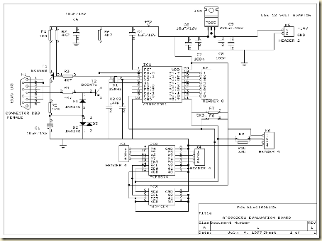
System circuit not Minimum Evaluation Board AT89C2051 and AT89C4051
Maybe we are more familiar with the term Minimum System AT89C2051 circuit, but this time I present a circuit which is not only a series of Minimum System AT89C2051 but more than that.
RS-232 interface, DB-9
Header for LCD display
I2C, PCF8574 I / O extender
AT24C04, I2C EEPROM
Next full text...
The circuit is more deserves to be called Evaluation Board AT89C2051 and AT89C4051. Some of the advantages of circuit Minimum System AT89C2051 / AT89C2051 and AT89C4051 Evaluation Board which I was present this time, hardware-hardware support below:
RS-232 interface, DB-9
Header for LCD display
I2C, PCF8574 I / O extender
AT24C04, I2C EEPROM
600W subwoofer audio amplifier with 20 channel mixer and parametric
This picture below is about my setup subwoofer amplifier with 20 CH mixer and parametric. This amplifier use transformer 10 ampere to supply the power and 3 ampere transformer use to supply mixer and parametric.Elco capacitor that i use for the transformer 10 A, only 10000uF numbered 2. The circuit of amplifiers that i use which is 600 watt mono subwoofer amplifier . And booster amplifier only use 2 Sanken transistors. See picture subwoofer amplifier assemblies below :
 |
| Looked over the side |
 |
| Front view |
 |
| Back top |


Subscribe to:
Posts (Atom)