Wednesday, January 29, 2014
Fish caller electronics circuit
For those of you who like fishing, this circuit is very suitable for you implement, because it can call the fish and collect a lot of fish so it is easy to provocation and get a lot of fish. Vibrations are excluded from this circuit reaches a distance of several meters in a circle. You can use the river, of where many fish that are easy to find except at sea the waves are fast , so this circuit will not work because it lost by the waves of the sea .Actually , can also be used at sea was calm but the water should not be too choppy.

Part List:C1 = 10nFC2 = 47uF/16VVR1= 5KR2 = 470RS1 = Switch On/offQ1 = BC160T1 = Transformator Output (OT)G1 = 3V batteryHow to use the Fish caller circuit :Ater the circuit is finished and sounds biased, then put inside the bottle and sealed for later when inserted in the water is not damged. After the circuit was put into bottles and then put into water, wait several seconds after the switch on/off button. After this circuit work the fish will come and surround this tool. And when its like that then its time to fishing.
Tuesday, January 28, 2014
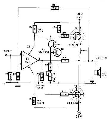
Circuit 150W amplifier with active crossover

Series 150W Amplifier With Active Crossover Series 150W Amplifier with Active Crossover is very interesting. Actually, this circuit uses 4-channel power amplifier chip. Well, as an Active Crossover here we use also a chip that can separate the tone of the bass, midrange and treble, the output from the Active Crossover can be directly amplified by power amplifier.
Power Chip 4-channel amplifier that we use is SANYO LA47536 who have power outputs up to 150W, while for Active Crossover (Active Crossover) we use the LF353 from National Semiconductor.

Monday, January 27, 2014
Parallel Port Relay Interface
Below are three examples of controlling a relay from the PCs parallel printer port (LPT1 or LPT2). Figure A shows a solid state relay controlled by one of the parallel port data lines (D0-D7) using a 300 ohm resistor and 5 volt power source. The solid state relay will energize when a "0" is written to the data line. Figure B and C show mechanical relays controlled by two transistors. The relay in figure B is energized when a "1" is written to the data line and the relay in figure C is energized by writing a "0" to the line. In each of the three circuits, a common connection is made from the negative side of the power supply to one of the port ground pins (18-25).
Parallel Port Relay Interface Schematic

There are three possible base addresses for the parallel port You may need to try all three base addresses to determine the correct address for the port you are using but LPT1 is usually at Hex 0378. The QBasic "OUT" command can be used to send data to the port. OUT, &H0378,0 sets D0-D7 low and OUT, &H378,255 sets D0-D7 high. The parallel port also provides four control lines (C0,C1,C2,C3) that can be set high or low by writing data to the base address+2 so if the base address is Hex 0378 then the address of the control latch would be Hex 037A. Note that three of the control bits are inverted so writing a "0" to the control latch will set C0,C1,C3 high and C2 low.
Parallel Port Relay Interface Schematic
There are three possible base addresses for the parallel port You may need to try all three base addresses to determine the correct address for the port you are using but LPT1 is usually at Hex 0378. The QBasic "OUT" command can be used to send data to the port. OUT, &H0378,0 sets D0-D7 low and OUT, &H378,255 sets D0-D7 high. The parallel port also provides four control lines (C0,C1,C2,C3) that can be set high or low by writing data to the base address+2 so if the base address is Hex 0378 then the address of the control latch would be Hex 037A. Note that three of the control bits are inverted so writing a "0" to the control latch will set C0,C1,C3 high and C2 low.
Sunday, January 26, 2014
Simple Inverter with Two Transistors
The series below is a simple inverter circuit that will change the voltage of 12v dc to 220v ac, with use drive transistor 32 as its tip.
Inverter circuit is very simple and easy to assemble and is perfect for just starting to learn to assemble electronic circuits, you can use the transformer 2A to produce about 20 watts output. Do not forget to install coolers in its transistors. good luck.
Inverter circuit is very simple and easy to assemble and is perfect for just starting to learn to assemble electronic circuits, you can use the transformer 2A to produce about 20 watts output. Do not forget to install coolers in its transistors. good luck.

Saturday, January 25, 2014
TV Protect Circuit Dead or Damaged
Television set equipped with a circuit protector, then there are several possibilities that could occur if there is a problem on one of the circuits. Protect circuit horizontal part - When turned on the horizontal plane will live for a while, but then died again. At the time of death when measured on the horizontal driver indicates that no drive signal. If the power jack unplugged then try to turn on again then repeated a similar incident will happen again. But if if the base of the transistor or transistor try to open removable drive signal was viable.
Protect circuit of microcontroll - If checked the voltage at pin microcontrol power on-off control, power control is turned on when the plane going "on" for a while then back "off". If you unplugged the power jack will power "on" again, but briefly and then keep coming back "off". On certain models sometimes die when the aircraft was marked with the blazing LED indicators blink. Protect circuit tube - aircraft can be turned on but a dark raster.
 |
| Protect IC |
Tested voltage raster screen can be raised to normal flame or flame a horizontal line. Protect circuit the power supply - if enabled aircraft B + voltage of power supply there for a while but then lost or drops. Or the power supply voltage drops and there is but little rocking voltage, which is caused due to power supply to the death over and over again and again. There are models of televisions that do not use the protector system at all, there is only one system that uses a surge protector, but there are also some systems which use a surge protector as well. System protectors are made available for specific purposes. Keep track of the damage that led to protect circuit is sometimes difficult, because it always turns itself off the plane before we can make measurements. By getting to know a wide range of system protectors and understand how it works it will help overcome these difficulties.
Various kinds of protectors television system:
- Protectors x-ray
- Vertical Protectors
- Protectors B + over current (OCP)
- Protectors B + over voltage (OVP)
- ABL Protectors
- Supply voltage surge protector (if short or broken)
- Protectors white balance
- Protectors circuit power supply (SMPS)
Friday, January 24, 2014
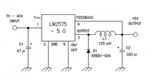
5 Volt Switching Regulator Power Supply
The switching regulator power supply used LM2575-5.0 on this schematic.
You can make the stable voltage by using the 3 terminal regulator like LM317. However, because the output electric current and the inputted electric current are the same approximately, the difference between the input electric power (The input voltage x The input electric current) and the output power (The output voltage x The output current) is consumed as the heat with the regulator. Because it is, the efficiency isn�t good.
You can make the stable voltage by using the 3 terminal regulator like LM317. However, because the output electric current and the inputted electric current are the same approximately, the difference between the input electric power (The input voltage x The input electric current) and the output power (The output voltage x The output current) is consumed as the heat with the regulator. Because it is, the efficiency isn�t good.
Data sheet for LM2575
SIMPLE SWITCHER 1A Step-Down Voltage Regulator
http://www.national.com/pf/LM/LM2575.htm
Thursday, January 23, 2014
Read Only Memory
Memory group called Read Only Memory also has characteristics that match the name. Existing data in ROM, this is data that has been entered by the manufacturer. The data already contained in it can not be changed again through the normal process, and can only be read only. There are pieces of data in ROM is used for the identity of the computer itself. It is stored in the BIOS (Basic Input Output System). There are also data contained in this module was first accessed by a computer when it boots. Sequences contained in this module and are accessed the first time when the computer is turned on is called bootstrapping.
In this bootstrap process, carried out some instructions such as checking the internal components supporting the work of at least one computer system, such as checking ALU, CU, BUS supporter of the motherboard and processor, check the main BIOS, check the graphics card BIOS, check the Memory Module, check for the presence Secondary Storage which can be a floppy disk, hard disk, or CD-ROM drive, then just check the MBR (Master Boot Record) of the storage media designated by the BIOS (in the Boot Sequence). The following will be discussed types of ROM and its development.
PROM (Programmable ROM)
ROM provides an opportunity for users to modify data stored by default. A device called PROM programmer in charge of "burn" (burn in) this chip. With a strong electric current bit location will burn and showed a value (0 or 1). After going through the process burningin, this PROM can no longer be changed contents.
EPROM (Erasable Programmable ROM)
This chip is the development of PROM. Only, this EPROM can be erased its previous contents using ultraviolet light. These rays pass through a gap in the collection of chips. Thus, the charge stored can be released. In other words, EPROM can be erased with ultraviolet light and reprogrammed electrically.
EEPROM (Electrically Erasable Programmable ROM)
This chip is not much different from the EPROM, EEPROM data but can be removed without the use of ultraviolet light. Just use electrical pulses (electrical pulses). Types of ROM such as PROM, EPROM and
EEPROM memory is classified into stable (nonvolatile memories). That is, these three types of ROM memory will keep its data even when not fed by electrical current. In development, the EEPROM chip has been used for the BIOS of a motherboard. By using the technique of "flash", the contents of the BIOS can be made later (update). However, the danger of flashable BIOS is all people can change the contents, including viruses. If you have been changed by a virus, then used a computer motherboard that will not be used again.
Wednesday, January 22, 2014
The Alpine Car Stereo
We all know that brand names matter when purchasing car audio hardware. There are brands that are surely more reputable than others. When you are at the store and they offer choice after choice after choice, suddenly you feel overwhelmed on what really to buy. But you can be assured of one thing, if they offer you an Alpine car stereo you can’t go wrong with it.
 Alpine car stereo and electronics, founded in 1978, is a world leader in the industry of high performance mobile electronics. They specialize in mobile multimedia, an integrated system approach incorporating digital entertainment, security and navigation products for the mobile entertainment.
Alpine car stereos are a new breed of units which feature the convergence of high performance audio, video, navigation and telematics in the form of Mobile Multimedia. Navigation systems act as the resource center of the Alpine car stereo Mobile Multimedia lineup. Intelligent Transportation Systems (ITS), DVD players, Dolby Digital systems, satellite digital audio radio, mobile data linking and communication through telematics devices will be fused with navigation systems to create a platform of products. Mobile Multimedia integrates Alpines innovative audio, video, security and navigation products, as well as its new GUI for Drivers, human interface and information communications technology.
 To grasp what the Alpine car stereo Mobile Multimedia is, take a look at the IVA-D901 Alpine car stereo Mobile Multimedia Station/CD/DVD Receiver/Ai-NET Controller.
The IVA-D901 has 400% more pixels than a conventional in-vehicle display, meaning that it has 1.15 million pixel elements. It has 50W x 4 built-in power and 3 PreOuts (4 volt), SAT Radio ready, a Hard Disc Drive (HDD), and Alpine car stereo Navigation. Key features include:
- 7" Fully Motorized Wide Screen Monitor
- 18W x 4 MOSFET Amplifier
- Built-in Dolby Digital/DTS Decoder
- Bass Engine® Plus
- Subwoofer Level Control
- Bass Center Frequency Control
- Bass Band Width Adjustment
- Treble Center Frequency Control
- Subwoofer Phase Selector
- Bass Type Control
- 4-Ch Digital Time Correction
- 3 Position 12 dB/Oct Crossover
- MediaXpander™
- SAT Radio Ready
- MP3 Text Information Display
- Quick Search Function
- CD/CD-R Playback
- CD Text, Text Display, Text Scroll
- M DAC
- MaxTune SQ Tuner
- 3 Auxilliary A/V Inputs with Remote Control Input
- Dedicated Navigation Input
- Dedicated Camera Input
- 2 Auxilliary Monitor A/V Outputs
- Navigation Audio Mix
- 3 PreOuts (4 volt)
- MM Driver (Hard Disc Drive) Ready
- MobileHub Ready
- Ai-NET Control Center DVD/CD/MP3 Changer Controller
- "Digital Art" Spectrum Analyzer Display
- RUE-4190 Universal Wireless Remote Control Included
If these all seems too much for you, Alpine car stereos also have more conventional head units to offer. The CDA-9835 Alpine car stereo In-Dash CD Player/Ai-Changer Controller lets you fully customize both illumination and sound, with a range of 512 colors and super-versatile Bass Engine functions like digital time correction and parametric EQ. You can download audio parameter settings and connect and control as many as eight amps. The BioLite display, Menu key and rotary knob make operation extremely easy.
Like most Alpine car stereo units, it is also SAT Radio Ready, giving you a much greater choice of listening options than ordinary local AM/FM radio. You can select from among a wide range of music genres, news, sports, and talk programs with digital quality anywhere.
Tuesday, January 21, 2014
1200 Watt Subwoofer Energy ESW M8 NA
 One of the most important speakers in any system, the subwoofer is often relegated to a back corner and nearly forgotten. At Energy, however, we invest a great deal of design time and effort into building the industry’s best subwoofers, offering unparalleled performance and flexibility. The ESW-M8 is no exception. The ESW-M8 subwoofer delivers deep, accurate effects with 1200 peak watts of room-filling power—all from a 9-inch cube.
The ESW-M8 features an 8-inch anodized aluminum cone woofer with Ribbed Elliptical Surround for tight and powerful bass response and two 8-inch anodized aluminum cone passive radiators that eliminate port noise that allows for deep bass extension. With a variable low pass filter of 50Hz-200Hz, you get versatile blending using the built-in crossover or your surround processor. The furniture grade high gloss black cabinet provides versatility and will blend into your décor. It’s the ideal companion to any front, center, and surround channels, whether you’re looking to achieve a 5.1 system or a 5.1 on the Richter scale.
Ribbed Elliptical Surround
This tiny beast features our patented Ribbed Elliptical Surrounds, which mates perfectly with a powerful amplifier to provide your audio experience with plenty of pure bass. The Ribbed Elliptical Surrounds that encircle Energys products woofers are unlike any other. By changing the shape of the speaker surround to an ellipse, rather than the traditional "half roll," distortion is reduced dramatically. Side benefits include increased excursion and larger piston area, allowing for greater efficiency. Energys cast basket woofers also feature this technology, allowing the surround to stretch and contract as it moves, eliminating dimpling.
Selectable Auto Power Switch
The featured power switch can be set to either On, Off or Auto. If the switch is in the Off position, the subwoofer will not power up. If the switch is in the On position, it will constantly remain on. If the switch is set to the Auto position, when a signal is present the subwoofer will turn on and will automatically turn off several minutes after a signal is no longer present.
Low-Pass Filter and Phase Controls
The low-pass filter control allows for the adjustment of the low-pass filter. Adjustments can infinitely be made from 50Hz to 200Hz. This will determine the highest frequency that the subwoofer will reproduce for a custom sound fitted to your room. Setting the crossover too low will create a gap between the frequency response of the front speakers and that of the subwoofer, while setting the crossover frequency too high will create a doubling of certain frequencies, making the music sound boomy.
The phase control switch allows for the adjustment of the phase of the subwoofer, in relation to the speakers used in your system, from 0 to 180 degrees, to give your home theater system the right balance. This control ensures that the subwoofer operates in phase with the rest of the system, as an out of phase subwoofer will either sound like it is lacking in bass performance or that its timing is off. This setting will be determined by your listening position, the characteristics of your listening room and its interaction with your Energy subwoofer.
About Energy
Energy, admittedly, is a bold name for a speaker. Fortunately for you, you’re looking at some highly dynamic audio generators. We’re talking crystal clear dialogue. Big booms, bangs, and ka-thuds from your favorite flicks. And music that’ll rock your soul. That’s what you get when teams of dedicated engineers work alongside expert designers. For more than 30 years, they’ve been researching the scientific principles of sound and using the most modern materials available. They’ve fine-tuned each speaker according to the three major aspects of loudspeaker performance: wide dispersion, low distortion, and flat frequency response. And they’ve customized and re-customized every little component, resulting in one-of-a-kind modifications like our patented Ribbed Elliptical Surrounds, for better bass, and the Convergent Source Module (CSM), for accurate sound. And, while all that audio research is great, in the end all that matters is that when you crank the volume, what you’ll hear is sound perfected. What you’ll feel is pure Energy.
Monday, January 20, 2014
Atmel microcontroller Easy Downloader Circuit
Easy Downloader Circuit
Atmel microcontroller series AT89Cxx51 Easy Downloader is one of the downloader that is often used to write data to program the Atmel microcontroller AT89CXX51. Easy Downloader AT89Cxx51 ATMEL microcontroller is using the serial port as a channel of communication with the computer.

Easy Downloader ATMEL Microcontroller AT89Cxx51 can be used to program Atmel AT89CXX51 in parallel. Atmel microcontroller series AT89Cxx51 Easy Downloader is quite simple to make your own because the components necessary to membutanya not complex. Atmel microcontroller series AT89Cxx51 Easy Downloader do not support the serial programming microcontrollers ISP. In the article Easy Downloader ATMEL Microcontroller AT89Cxx51 only displays images Easy Downloader Microcontroller series from Atmel AT89Cxx51 only and are simple.
Sunday, January 19, 2014
Megabass Circuit with TL072
The following is megabass circuit schematic (Mega Bass Circuit) . The megabass circuit is a modified Baxandall tone control with no bass cut and no treble control. It boosts frequencies from about 30Hz to 160Hz can boost by 14dB.
Megabass Schematics

Note:
The input capacitor can be replaced with a .01uf cap if you wish.
The 10pf capacitor is optional and will start rolling off everything over 15kHz. 5pf will double this to 31kHz.
The tone control requires a low impedence input. If you already have a low impedence input, the input buffer can be removed. However, the output is inverted.The opamp is not critical. A 4558 would be just fine.
I do not show the parts for the +4.5 reference. Here is the +4.5 voltage divider I used.
IC A4558 Pinning
The A4558 is a monolithic Integrated Circuit designed for dual operational amplifier.
Absolute maximum ratings of A4558 Ap-amp
Supply voltage VCC 20 or ±10 V
Differential input voltage VIND 20 V
Input voltage VIN ±10 V
Power Dissipation PD 300 mW
Operating temperature Topr -45 ~ +85 °C
Storage temperature Tstg -55 ~ +150 °C
Saturday, January 18, 2014
Reducing Treble tone circuit
Treble reducer circuit above is an example of a simple circuit and is suitable to be used as experimental material and analysis of the workings of the circuit.

As I mentioned earlier the bass reducer series, this series actually has the same working principles with a series of bass reducer. Where these circuits utilize capacitors nature of the charge and discharge. The difference of the damping function obtained from the difference of the capacitor. If the series bass reducer series capacitors are mounted on the op-amp input lines, while in this treble reducer series capacitors are mounted parallel with the strengthening of the op-amp prisoners. Installation of this circuit has a parallel in the work analysis in contrast with the installation of the series on a series of bass reducer. The difference is that the installation of the series, so we URLs that are easy to understand how a wire working capacitors for high frequency signal, so with high frekuesni so automatic signal to be passed to the output terminal by a capacitor. But if we put a parallel between the output capacitor with the terminals, then automatically because the capacitor is considered as a wire so the voltage on the capacitor is near 0 volts, so the output voltage will also follow the voltage on the capacitor because they connect parallel. As with the low frequency signal, the capacitor is considered open and makes voltage wire that fell to him is to approach the input voltage. To understand how the capacitor can be regarded as a wire or an open switch I mentioned in my post about the working principles of capacitors and a series of bass reducer.
Indeed, when examined in detail, not only the capacitors that play a role here but the component resistors and op-amp also affect. But I can confirm that the main function is performed by a capacitor reduction. Series resistors are intended to be installed that will flow into the capacitor can be adjusted so that it influences the charge and discharge the capacitor will make the appropriate damping.
Take a look at the picture above the treble reducer circuit and also the image output signal. There are two function generator as input and has a signal with different frequencies. The first signal of amplitude 1 volt and low frequencies, the two signals with an amplitude of 1 volt and with high frequency. At the time of our input select switch position to the relationship with the input low frequency signal, the signal output will be nearly equal to the input signal such as no change. Whereas if we switch position to link high-frequency input signal then the output signal amplitude will be damped near 0 volts.
Example treble reducer circuit is very simple and can you develop more in accordance with the desires and your needs. At least with understanding the working principle of this circuit we can apply a time when we are required to perform the function of damping trebele.
Thursday, January 16, 2014
Automotive Ignition Coil Buzz Box
This picture is a circuit for a buzz coil using a standard car battery to create. Dual timer IC 556 is used to set the frequency and the duty cycle of the coil current to be determined. One of the timer is used as an oscillator for generating the rectangular waveform 200 Hz to control (IRF740 MOSFET), while the second timer is stopped and the oscillator switching points are opened and closed (closed = a). The result is a steady stream of sparks of the ignition coil a distance of about 5 milliseconds, while the switching points are closed. Operation: Pin 8 and 12 the trigger inputs, and a timer which are driven by the points and an inverted signal of the clock output (pin 9) to produce.
Automotive Ignition Coil Buzz Box Circuit Diagram

When the pin 9 is grounded points high, and vice versa. The signal on pin 9 controls the reset line (pin 4) of the second timer and keeps the output at pin 5 is low, while pin 4 and pin 8 is low and 12 high (still open). The 15K and 47K resistors and capacitors are 0.33uF synchronization components that the frequency and duty cycle of the second clock, which is about 4 milliseconds to 2 milliseconds apart to secure positive and negative. During the time interval is positive, the doors are always high MOSFET causing the coil to the current height of about 4 amps. This equates to approximately 80 milli joules of energy in the coil is released in the spark plug when the clock output (pin 5) moves on the ground, turn off the MOSFET. A zener diode 12 volts is placed on the node 10 and 27 ohms for the MOSFET gate input is above or below 12 volts -0.7 volts. A Zener diode 200 volts / 5 W used for the drain voltage of the MOSFET 200 and limit the useful life of the spark to expand.
The circuit must operate reliably with a jumper, but the circuit operation with no load applied (the son of candle down, etc.) may cause a malfunction, because most of the energy absorbed by the Zener. You can also use a transient voltage suppressor (TVS) as 1.5KE300A 1.5KE200A or instead of the zener. This is probably a good hand, but difficult to obtain.
Automotive Ignition Coil Buzz Box Circuit Diagram
The circuit must operate reliably with a jumper, but the circuit operation with no load applied (the son of candle down, etc.) may cause a malfunction, because most of the energy absorbed by the Zener. You can also use a transient voltage suppressor (TVS) as 1.5KE300A 1.5KE200A or instead of the zener. This is probably a good hand, but difficult to obtain.
Wednesday, January 15, 2014
Flashing light uses triacs
This flashing light circuit uses triacs to generate an intermittent light with patchy frequency. extra components are the D1 diode and semi modifiable potentiometer R2. The trigger capacitor C1 is increased from 0.1 µF to 220 µF so to the triacs can be real prepared pro several successive periods. C1′s loading measure is longer, so to the lamp flashes with single pause of several periods.
 |
| Flashing light uses triacs Schematic |
Blinking frequency can be adjusted with P1. Semi-adaptable potentiometer R2 regulates the current gate. This setting affects the lighting duration of the lamp since it moreover find out the C1′s discharging spell.
Tuesday, January 14, 2014
Universal Battery Charger Based on LM317
This universal battery charger is based on LM317 and has an adjustable regulated output voltage and also has an adjustable constant-current charging circuit that makes it suitable to use for charging most NiCad batteries and some other types of batteries . This LM317 universal battery charger can charge a single cell or a number of series-connected cells up to a maximum voltage of 18 V.
This universal battery charger circuit use just some common electronic components like LM317 regulator , operational amplifier and some 2n3055 power transistors .2n3055 power transistors Q1 and Q2 are connected as series regulators to control the battery chargers out¬put voltage and charge-current rate. The LM317 used as an adjustable voltage regulator supplies the drive signal to the bases of power transistors Q1 and Q2.

By turning the potentiometer R9 the output-voltage level will be modified. A current-sampling resistor, R8 (a 0.1-fi, 5-W unit), connected between the negative output lead and circuit ground.As the charging voltage across the battery begins to drop, the current through R8 decreases , then the voltage feeding pin 5 of U3 decreases, and the comparator output follows, turning Q3 back off, which completes the signals circular path to regulate the batterys charging current. The charging current can be set by adjusting R10 for the desired current.
This universal battery charger circuit use just some common electronic components like LM317 regulator , operational amplifier and some 2n3055 power transistors .2n3055 power transistors Q1 and Q2 are connected as series regulators to control the battery chargers out¬put voltage and charge-current rate. The LM317 used as an adjustable voltage regulator supplies the drive signal to the bases of power transistors Q1 and Q2.
By turning the potentiometer R9 the output-voltage level will be modified. A current-sampling resistor, R8 (a 0.1-fi, 5-W unit), connected between the negative output lead and circuit ground.As the charging voltage across the battery begins to drop, the current through R8 decreases , then the voltage feeding pin 5 of U3 decreases, and the comparator output follows, turning Q3 back off, which completes the signals circular path to regulate the batterys charging current. The charging current can be set by adjusting R10 for the desired current.
Monday, January 13, 2014
Wireless receiver microphone circuit

Audio FM receiver module only requires a 5 volt DC voltage source and a potentiometer P2 to set the threshold level of noise that will be muffled. Voltage source to an audio FM receiver module is also to go through the regulator is good, because if the quality of resources kuran it will generate noise. At the output line installed capacitors C3 and C4 as a couple and compensator for output in accordance with the amplifier or mixer (100mV rms).

Part Series FM Wireless Microphone Receiver Hi Fi
To provide an output signal according to the needs and stable output signal audio FM receiver module on FM Wireless Microphone Receiver Hi Fi is fed to an audio preamplifier which uses IC TLC272. Levelk audio signal set by potentiometer P1. As a voltage regulator for power source circuit FM Wireless Microphone Receiver Hi Fi LM7805 regulator IC is used.

Sunday, January 12, 2014
Inverter 12V to 115V with 25 W power output
Low power inverter schematic are only use 9 components , one of which IC 556 , TIP120 NPN Darlington transistor.And turns 10 to 16 Vdc into 60 HZ, output 115 V square-wave power to operate ac equipment up to 25 W. In the circuit first ic originally hires as a timer chip m for stabilizatiom oscilator with components R1 and C1 setting frequency oscilator. Then the two transistor driver, drive the transformer push-pull fashion, When one transistor is biased on , the other circuit cut-off . The transformer is a 120V/18Vct unit that is connected backwards, so that it steps the voltage up rather than down. Oscilator circuit operates from about 4 to 16 V for stable output.
Part List :
R1 = 1K
R2 = 12K
R3 = 1K
R4 = 1/4W
C1 = 1uF
IC = 556
Q1 = TIP120
Q2 = TIP120
T1 = 120V 18VCT

Saturday, January 11, 2014
Sony Car Stereo
The Sony Corporation, based in Tokyo is a leading manufacturer of audio, video, communications, and information technology products for the consumer and professional markets. Their music, motion picture, television, computer entertainment, and online businesses also make Sony one of the most comprehensive entertainment companies in the world.
So it is not surprising to learn that Sony car stereos are also well renowned in the automotive audio market. In 2005, Sony car stereos launched their latest carrier car audio product, the Sony car stereo Xplod series which has an amazing lineup of head units, speakers, amplifiers, subwoofers, changers and accessories. It is impressive both in performance and aesthetic value.
 |
| Sony car stereo Xplod Series |
A good head unit from the Sony car stereo Xplod Series is the CDX – M9900 CD Receiver/Changer Controller/MP3 Player which boasts these features:
- 32,000-color TFT display
- Video Input for External Source Playback
- CD/CD-R/CD-RW/MP3 playback
- 4-Volt F/R/Sub Preouts w/HPF & LPF
- 52W x 4 High Power
- CEA-2006 Power Compliant
- CD/MD Control, CD Text
- XM Ready
- BBE MP, DSO, EQ7
- Auxiliary Input
- 1-bit D/A Converter
- Drive-S with 120dB S/N Ratio
- SSIR-EXA tuner, 18FM & 12AM presets
- Red key illumination
- Supplied wireless card remote (RM-X145A)
- Optional wireless rotary remote (RM-X6S)
- Optional wired rotary remote (RM-X4S)
This Sony car stereo goes best installed with matching items from the Xplod series such as:
Sony car stereo XS – V6941H 6 x 9” 4 - Way Speakers:
- 6 x 9" HOP Woofer Cone
- Stroke Stabilizer Surround
- 2-5/8" Cone Mid
- 1" Balanced Dome PEI Tweeter, Super Tweeter
- 400W Peak Power (100W RMS)
- Flexible Mounting Options
Sony car stereo XM-2100GTX 2/1 Channel Amplifier:
- 600W Max Power
- 100W x 2 RMS into 4 ohms, 20Hz-20kHz @ 0.04% THD
- 250W x 1 RMS into 4 ohms, 20Hz-20kHz @ 0.1% THD
- CEA-2006 Power Compliant
- Variable 50 - 300 Hz low pass filter
- 40 Hz EQ boost
- MOSFET power supply
- RCA & speaker level inputs
Sony car stereo XS-L102P5 10” Subwoofer:
- 10" Polypropylene Cone
- 1200W Peak Power (330W RMS)
- Unique cone design offers superior rigidity
- Gold-plated Binding Posts
- Small sealed/bandpass enclosure optimized
- 4-Ohm Voice Coil
- 2005 Subwoofer Parameters
Like other modern car audio manufacturers, the Sony car stereo also offers video capable units for playing VCDs, DVDs. A good item from the Sony car stereo Dream System Series is the MV - 900SDS Mobile DVD Dream System.
- 9" wide screen TFT display with swivel function
- DVD/CD-R/RW/VCD/MP3 Playback
- Built-in wired FM modulator
- Reversible display image
- Slot-load DVD Mechanism
- Memory Stick® media for playback of JPEG, MPEG, MP3
- Built-in Stereo Speakers
- A/V Input
- A/V Output
- Optical Digital Output (Dolby Digital®, dts®)
- IR transmitter for wireless headphones
- 2 sets of wireless headphones included
- Wireless card remote included
This unit is encased in a grey metallic finish and is ideally attached on the ceiling of the vehicle.
It is also an amazing fact that a lot of enthusiasts also incorporate the PlayStation into their Sony car stereos, which is probably one of the reasons why the Sony car stereo system has earned quite a following.
Friday, January 10, 2014
DC Servo Motor Controller
As we presented in another article the A3952S integrated circuit ( designed by Allegro MicroSystems ) can be used to design very simple and useful motor driver circuits . In the precedent article was presented a simple bipolar stepper motor driver circuit that use two A3952S circuits. As we presented in that article , the A3952S is capable of continuous output currents up to 2 A and operating voltages range up to 50 V.
DC Servo Motor Controller Circuit diagram

Warning , the 50 operating voltage is to power the motor , for the logic controller you will need a 5 volts Dc power supply .
This circuit presents a simple DC servo motor application that can be used in various electronic projects . As you can see in the circuit schematic this Dc servo motor driver schematic circuit use just one integrated circuit and other few external electronic components . With bidirectional dc servo motors, the PHASE terminal can be used for mechanical direction control. Similar to when braking the motor dynamically, abrupt changes in the direction of a rotating motor produce a current generated by the back EMF. The current generated will depend on the mode of operation.
DC Servo Motor Controller Circuit diagram
This circuit presents a simple DC servo motor application that can be used in various electronic projects . As you can see in the circuit schematic this Dc servo motor driver schematic circuit use just one integrated circuit and other few external electronic components . With bidirectional dc servo motors, the PHASE terminal can be used for mechanical direction control. Similar to when braking the motor dynamically, abrupt changes in the direction of a rotating motor produce a current generated by the back EMF. The current generated will depend on the mode of operation.
Thursday, January 9, 2014
SD2 Smoke Detector
This smoke detector circuit diagram is based on the SD2 CMOS Photo-Electric Smoke Detector Integrated Circuit manufactured by Supertex INC and include almost all needed components to build a very simple and high efficiency smoke detector project .As you can see , this smoke detector circuit diagram is very simple an require few external components .
SD2 Smoke Detector Circuit diagram

 The LED predriver output pulses an external transistor which in turn, switches on the infrared light emitting diode at a very low duty cycle. The desired IR LED pulse period is determined by the value of the externai timing resistor. The Smoke Sensitivity is adjustable through a trimmer resistor which varies the IR LED puise width. The light sensing element is a silicon photovoltaic cell which is held at near zero bias to minimize leakage currents. The circuit can detect signals as low as 1 mV and generate an alarm. The IR LED pulse repetition rate increases when smoke is detected. The IR diode can be RCA Type SG 1010A or Spectronics Type SE 5455-4 Clairex and the IR Photo detector can be Vactec VTS4085 .
Because the SD2 CMOS Photo-Electric Smoke Detector IC is designed for use in low power, battery operated, consumer applications it needs a 9 volts DC power supply (or a 9 volts battery ).
SD2 Smoke Detector Circuit diagram
Because the SD2 CMOS Photo-Electric Smoke Detector IC is designed for use in low power, battery operated, consumer applications it needs a 9 volts DC power supply (or a 9 volts battery ).
Mosfet Amplifier 20Watt Output Power
This audio amplifier showed in this circuit diagram , is a very simple and efficiency audio amplifier circuit based on the TDA1308 integrated class-AB stereo headphone . The device is fabricated in a 1 mm Complementary Metal Oxide Semiconductor (CMOS) process and has been primarily developed for portable digital audio applications.
You can use this circuit diagram with TDA1308 or TDA1308A , the difference between the TDA1308 and the TDA1308A is that the TDA1308A can be used at low supply voltages. The maximum output power that can be obtained with this circuit is around 80mwatts. This audio amplifier circuit requires a very low voltage power supply : from 3 to 7 volts for single supply or 1.5 to 3 volts for dual supply , for TDA1308 .
The TDA1308A supports a low voltage input down to 1.2 volts , but the typical power supply required for both circuits is 5 volts for single supply and 2.5 volts for dual supply .
As you can see the circuit requires very few external components and can be configured to work in stereo or mono configuration.
Subscribe to:
Posts (Atom)