Wednesday, January 29, 2014
Fish caller electronics circuit
For those of you who like fishing, this circuit is very suitable for you implement, because it can call the fish and collect a lot of fish so it is easy to provocation and get a lot of fish. Vibrations are excluded from this circuit reaches a distance of several meters in a circle. You can use the river, of where many fish that are easy to find except at sea the waves are fast , so this circuit will not work because it lost by the waves of the sea .Actually , can also be used at sea was calm but the water should not be too choppy.

Part List:C1 = 10nFC2 = 47uF/16VVR1= 5KR2 = 470RS1 = Switch On/offQ1 = BC160T1 = Transformator Output (OT)G1 = 3V batteryHow to use the Fish caller circuit :Ater the circuit is finished and sounds biased, then put inside the bottle and sealed for later when inserted in the water is not damged. After the circuit was put into bottles and then put into water, wait several seconds after the switch on/off button. After this circuit work the fish will come and surround this tool. And when its like that then its time to fishing.

Tuesday, January 28, 2014
Circuit 150W amplifier with active crossover

Series 150W Amplifier With Active Crossover Series 150W Amplifier with Active Crossover is very interesting. Actually, this circuit uses 4-channel power amplifier chip. Well, as an Active Crossover here we use also a chip that can separate the tone of the bass, midrange and treble, the output from the Active Crossover can be directly amplified by power amplifier.
Power Chip 4-channel amplifier that we use is SANYO LA47536 who have power outputs up to 150W, while for Active Crossover (Active Crossover) we use the LF353 from National Semiconductor.

Monday, January 27, 2014
Parallel Port Relay Interface
Below are three examples of controlling a relay from the PCs parallel printer port (LPT1 or LPT2). Figure A shows a solid state relay controlled by one of the parallel port data lines (D0-D7) using a 300 ohm resistor and 5 volt power source. The solid state relay will energize when a "0" is written to the data line. Figure B and C show mechanical relays controlled by two transistors. The relay in figure B is energized when a "1" is written to the data line and the relay in figure C is energized by writing a "0" to the line. In each of the three circuits, a common connection is made from the negative side of the power supply to one of the port ground pins (18-25).
Parallel Port Relay Interface Schematic
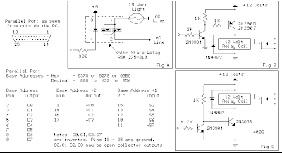
There are three possible base addresses for the parallel port You may need to try all three base addresses to determine the correct address for the port you are using but LPT1 is usually at Hex 0378. The QBasic "OUT" command can be used to send data to the port. OUT, &H0378,0 sets D0-D7 low and OUT, &H378,255 sets D0-D7 high. The parallel port also provides four control lines (C0,C1,C2,C3) that can be set high or low by writing data to the base address+2 so if the base address is Hex 0378 then the address of the control latch would be Hex 037A. Note that three of the control bits are inverted so writing a "0" to the control latch will set C0,C1,C3 high and C2 low.
Parallel Port Relay Interface Schematic
There are three possible base addresses for the parallel port You may need to try all three base addresses to determine the correct address for the port you are using but LPT1 is usually at Hex 0378. The QBasic "OUT" command can be used to send data to the port. OUT, &H0378,0 sets D0-D7 low and OUT, &H378,255 sets D0-D7 high. The parallel port also provides four control lines (C0,C1,C2,C3) that can be set high or low by writing data to the base address+2 so if the base address is Hex 0378 then the address of the control latch would be Hex 037A. Note that three of the control bits are inverted so writing a "0" to the control latch will set C0,C1,C3 high and C2 low.
Sunday, January 26, 2014
Simple Inverter with Two Transistors
The series below is a simple inverter circuit that will change the voltage of 12v dc to 220v ac, with use drive transistor 32 as its tip.
Inverter circuit is very simple and easy to assemble and is perfect for just starting to learn to assemble electronic circuits, you can use the transformer 2A to produce about 20 watts output. Do not forget to install coolers in its transistors. good luck.
Inverter circuit is very simple and easy to assemble and is perfect for just starting to learn to assemble electronic circuits, you can use the transformer 2A to produce about 20 watts output. Do not forget to install coolers in its transistors. good luck.

Saturday, January 25, 2014
TV Protect Circuit Dead or Damaged
Television set equipped with a circuit protector, then there are several possibilities that could occur if there is a problem on one of the circuits. Protect circuit horizontal part - When turned on the horizontal plane will live for a while, but then died again. At the time of death when measured on the horizontal driver indicates that no drive signal. If the power jack unplugged then try to turn on again then repeated a similar incident will happen again. But if if the base of the transistor or transistor try to open removable drive signal was viable.
Protect circuit of microcontroll - If checked the voltage at pin microcontrol power on-off control, power control is turned on when the plane going "on" for a while then back "off". If you unplugged the power jack will power "on" again, but briefly and then keep coming back "off". On certain models sometimes die when the aircraft was marked with the blazing LED indicators blink. Protect circuit tube - aircraft can be turned on but a dark raster.
 |
| Protect IC |
Tested voltage raster screen can be raised to normal flame or flame a horizontal line. Protect circuit the power supply - if enabled aircraft B + voltage of power supply there for a while but then lost or drops. Or the power supply voltage drops and there is but little rocking voltage, which is caused due to power supply to the death over and over again and again. There are models of televisions that do not use the protector system at all, there is only one system that uses a surge protector, but there are also some systems which use a surge protector as well. System protectors are made available for specific purposes. Keep track of the damage that led to protect circuit is sometimes difficult, because it always turns itself off the plane before we can make measurements. By getting to know a wide range of system protectors and understand how it works it will help overcome these difficulties.
Various kinds of protectors television system:
- Protectors x-ray
- Vertical Protectors
- Protectors B + over current (OCP)
- Protectors B + over voltage (OVP)
- ABL Protectors
- Supply voltage surge protector (if short or broken)
- Protectors white balance
- Protectors circuit power supply (SMPS)
Friday, January 24, 2014
5 Volt Switching Regulator Power Supply
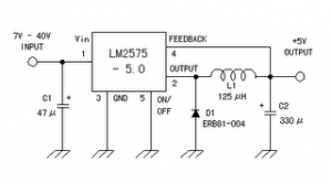
The switching regulator power supply used LM2575-5.0 on this schematic.
You can make the stable voltage by using the 3 terminal regulator like LM317. However, because the output electric current and the inputted electric current are the same approximately, the difference between the input electric power (The input voltage x The input electric current) and the output power (The output voltage x The output current) is consumed as the heat with the regulator. Because it is, the efficiency isn�t good.
You can make the stable voltage by using the 3 terminal regulator like LM317. However, because the output electric current and the inputted electric current are the same approximately, the difference between the input electric power (The input voltage x The input electric current) and the output power (The output voltage x The output current) is consumed as the heat with the regulator. Because it is, the efficiency isn�t good.
Data sheet for LM2575
SIMPLE SWITCHER 1A Step-Down Voltage Regulator
http://www.national.com/pf/LM/LM2575.htm
Thursday, January 23, 2014
Read Only Memory
Memory group called Read Only Memory also has characteristics that match the name. Existing data in ROM, this is data that has been entered by the manufacturer. The data already contained in it can not be changed again through the normal process, and can only be read only. There are pieces of data in ROM is used for the identity of the computer itself. It is stored in the BIOS (Basic Input Output System). There are also data contained in this module was first accessed by a computer when it boots. Sequences contained in this module and are accessed the first time when the computer is turned on is called bootstrapping.
In this bootstrap process, carried out some instructions such as checking the internal components supporting the work of at least one computer system, such as checking ALU, CU, BUS supporter of the motherboard and processor, check the main BIOS, check the graphics card BIOS, check the Memory Module, check for the presence Secondary Storage which can be a floppy disk, hard disk, or CD-ROM drive, then just check the MBR (Master Boot Record) of the storage media designated by the BIOS (in the Boot Sequence). The following will be discussed types of ROM and its development.
PROM (Programmable ROM)
ROM provides an opportunity for users to modify data stored by default. A device called PROM programmer in charge of "burn" (burn in) this chip. With a strong electric current bit location will burn and showed a value (0 or 1). After going through the process burningin, this PROM can no longer be changed contents.
EPROM (Erasable Programmable ROM)
This chip is the development of PROM. Only, this EPROM can be erased its previous contents using ultraviolet light. These rays pass through a gap in the collection of chips. Thus, the charge stored can be released. In other words, EPROM can be erased with ultraviolet light and reprogrammed electrically.
EEPROM (Electrically Erasable Programmable ROM)
This chip is not much different from the EPROM, EEPROM data but can be removed without the use of ultraviolet light. Just use electrical pulses (electrical pulses). Types of ROM such as PROM, EPROM and
EEPROM memory is classified into stable (nonvolatile memories). That is, these three types of ROM memory will keep its data even when not fed by electrical current. In development, the EEPROM chip has been used for the BIOS of a motherboard. By using the technique of "flash", the contents of the BIOS can be made later (update). However, the danger of flashable BIOS is all people can change the contents, including viruses. If you have been changed by a virus, then used a computer motherboard that will not be used again.
Subscribe to:
Posts (Atom)